Tagged: arduino
Blinking Blue- Powering a 3.7 volt LED from a 2.4 volt coin cell with a $0.02 charge pump

Everyone loves blue LEDs and everyone loves coin cell batteries, but if you want to power a blue LED from a coin cell you will need some help. Here is a super-cheap and easy way add a to boost your LED voltage with only an additional capacitor & diode, and a little software.

Bigger is better: Build an Arduino-powered monster scrolling LED sign for about $15 a foot

Would you do with a massive full color animated LED display? How about…
- Read your Tweets in giant 140 char gulps from a block away
- Add English sub-titles to the Eiffel Tower
- Display a live-updating, 45 digit long countdown of the number of atoms left in the known universe
What if you could build the display however long you needed it, for only about $15/foot?
What if it was really easy to build and used everyone’s favorite low cost micro-controller so you could easily change the software to do whatever you wanted?
Well you can! Read on for details and perfunctory video!

Getting Real – Using Blind Send SPI to Turbocharge the Adafruit DotStar Libraryspi,
Last time, we experimented with spiritual blind-sending as a way to theoretically speed up SPI on AVR. While there were lots of fancy oscilloscope traces and impressive demo code, there is nothing like an actual, real, practical application to get people excited. Read on to see how much faster we can make the already highly optimized AdaFruit DotStar library with a little blind-sending action… (spoiler alert – the answer is lots more faster!)
Continue reading

SPI with a Blindfold On- speed up by letting go and trusting the machine
Constantly checking to see if the coast is clear feels responsible, but it wastes cycles. Sometimes it is better to leap (or load) without looking. With a little hand-coded assembly, we can run our AVR processor lock-step with the SPI hardware and blindly dump new bytes into it at precisely the right moment. Because we don’t spend any time reading and testing status bits, we can increase the maximum throughput by more than 20%. If the prospect of screamingly fast yet perfectly safe SPI turns you on, read on…
Continue reading
AVR Timer-based One Shot Explained
Last time, we made one-shot pulses using the AVR’s built in hardware timer module. Today we are going to dive deep into the datasheets to see how this technique is able to coax the normally free-running timer into generating a single pulse. Along the way, we will learn about the low level rules that govern the operation of the timer, and use a trick or two to get around those rules. Read on!…
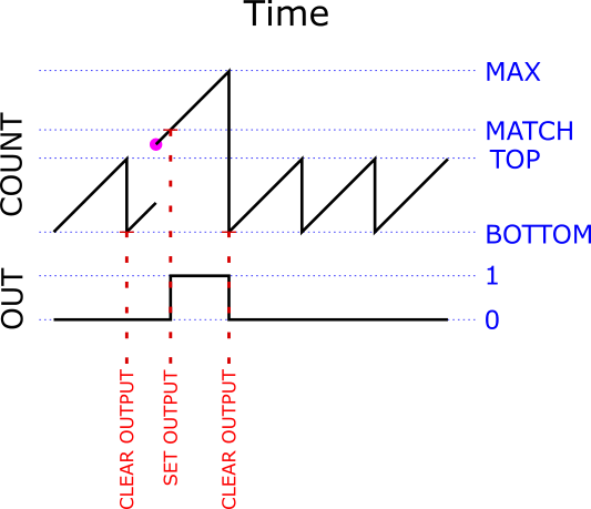
The Perfect Pulse- generating precise one-shots on AVR8

It is possible to generate one-shot pulses on an AVR that…
- Are as narrow as a single clock cycle (63 nanoseconds!)
- Are precise to a single clock cycle
- Will run to correct completion no matter what else the processor is doing 1
- Do not require you to turn off interrupts at all (!)
- Do not require any assembly code
These pulses are generated in pure hardware. They require a couple of instructions of interruptible code to fire. Once fired, they are completely autonomous and depend only on the system clock to run to completion.
Sound cool? Read on!
Save the Earth One Resistor at a Time – External pull-up resistor no longer needed for DS18B20 temp sensor
EXECUTIVE SUMMARY:
Using the updated Arduino 1-Wire library code presented here, you can eliminate the need for an external pull-up resistor for typical small networks of DS18B20 temperature sensors. This should also work with any AVR processor and other types of 1-Wire devices as well. You can download the updated 1-Wire library here…
https://github.com/bigjosh/OneWireNoResistor/archive/master.zip
The mythical “required” external pull-up

From the DS18B20 Data Sheet
If you’ve ever used the ubiquitous (and amazingly useful!) DS18B20 family of 1-Wire temperature sensors, you’ve almost certainly used a 4.7K ohm pull-up resistor as well. Every one of the seemingly endless Arduino DS18B20 tutorials on the web starts with some version of the line “You will not be able to do anything with this senor until you go out and procure yourself a 4.7K ohm resistor”. AdaFruit is even generous enough to include one of these resistors with every DS18B20-based temperature sensor they sell (be it bare, waterproof, or hi-temp) because they know you are going to need it.
I am here to tell you that everything is about to change. If you were banking on your stockpiles of 4.7K ohm resistors to be the one reliable store of value in these uncertain times, you need to rethink your long-term asset preservation strategy because the decade-long run of stable demand for this part is about to plummet. Yes – it is now possible to connect DS18B20 sensors without any external pull-up resistor at all!
Outrageous claims demand outrageous proof, so let’s start with a brief demo that proves beyond a shadow of a doubt that this is not just a cockamamie theory, but cold hard fact…
Temperature Logging to a Google Spreadsheet with an Arduino Yun
| UPDATE 8/7/2104:It appears that Google occasionally will randomly and silently drop the authorization for an Apps Script web app. If you notice that your spreadsheet has stopped updating and you know that your logger is still working, then you probably need to log into your spreadsheet from a web browser, go into the scripts editor, and manually execute any function in the script. This will cause a popup that will reauthorize the script and everything will then start working again.
I think this is the last straw. I can not recommend using Google for logging (or any other non-trivial application) any more. This stuff is just too flaky. Sorry. |
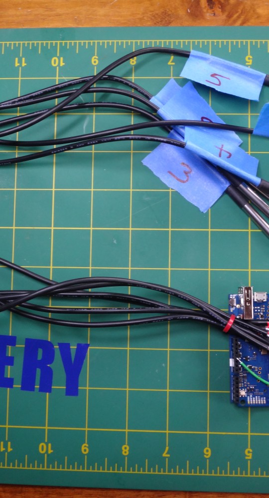
If you are like me, you often find yourself in a situation where you need to log multiple channels of temperature data. From testing nano-insulating paint to debugging an overheating geothermal well, most of us will have need of accurate and frequent temperature logs at some point in our short and brutish lives.
Here is a recipe to make a reliable, cheap, and easy cloud-based, multi-channel temperature logger using an Arduino Yun and DS18B20 temperature sensors. I chose the Yun because everyone loves Arduinos and this one can connect to the internets. I choose the DS18B20 sensors because they are awesome and cheap and accurate and you can hook up lots of them to a single pair of wires.
A platform for casual encounters with interactive technology – Making Noise
…you should be able to get this working about 2 minutes…
(Looking for Part 1 of this series?)
Next we are going to let people specify a value rather than just on or off. Let’s let them pick the frequency of a tone!
Here is what it looks like…
Step-by-step setup instructions…
- We will start with a stock Yun out of the box. You can reset your Yun back to this state by pushing and holding the “Wifi Reset” button for 30 seconds.
- Connect a speaker between pin 8 and ground on the Yun, like this…

- Connect the Yun to your computer – probably via USB. Make sure you select the correct port under Tools->Port and the Yun board under Tools->Board.
- Copy/paste the BeepMeSetup sketch [GET CODE] into your Arduino IDE and upload it to the Yun. You can connect via Serial Monitor in the IDE after the upload completes if you want to watch the action, but it is not necessary.
- Wait for the red LED to start blinking a steady once per second. This will let you know that the setup script has completed. It takes about a minute to finish – longer if you recently rebooted the board.
- Copy/paste the BlinkMe sketch [GET CODE] into your Arduino IDE and upload it to the Arduino Yun.
- Take out your cellphone and connect to the new BeepMe Wifi network coming from the Yun.
- Make some noise! Yeay!

The full code for this project is available on GitHub here.
HOW IT WORKS
To get the value from the webpage to the Arduino sketch, we added a new “TONE” command that consists of the letter “T” followed by a 5 digit number specifying the frequency of the tone. So, “T0100″ would request a 0100Hz tone.
First let’s a the new tone command to the Arduino sketch. Note we also have to increase the size of the command buffer since this new command can be 6 bytes long. Here is the updated Arduino code…
[code language=”c”]
// Connect a speaker here
#define TONE_PIN 8
// Forgiving parse of an unsigned int from a string. All non-digits simply ignored.
unsigned int parseUnsignedInt( const char *s , int len ) {
unsigned int x=0;
while (len–) {
if (isdigit(*s)) {
x*=10;
x+=(*s)-‘0’;
}
s++;
}
return(x);
}
// Understood command string formats:
// ‘Tnnnnn’ where nnnnn is 5 digit frequency specifier – Geneate a tone
// ‘N’ – Stop any playing tone
#define COMMAND_LEN 6
void processCommand( const char *commandString ) {
// Use the first byte to specifiy action…
switch (commandString[0]) {
case ‘T’: { // Generate a tone of the frequency specified by the 5 digit number after the action…
unsigned int freq = parseUnsignedInt( commandString + 1 , 5 );
if (freq >=50 && freq<=5000 ) { // Just some sanity checks…
tone( TONE_PIN , freq ); // Play the specified tone
}
break;
}
case ‘N’: { // Stop any currently playing tone
noTone( TONE_PIN );
break;
}
}
}
// This is the default baud rate for the serial link
#define LININOBAUD 250000
void setup() {
Serial1.begin(LININOBAUD); // open serial connection to Linino
}
// We to use this string to indicate where the command is inside the request string…
// Mast match the command string sent by the HTML code
#define COMMAND_PREFIX "COMMAND="
// This is the expected length of the incoming command. For now just turnong on/off so only need 1 bytes
char commandBuffer[COMMAND_LEN];
void loop() {
// Does this look like a command request?
if (Serial1.find(COMMAND_PREFIX)) {
// Read it into the command buffer and only process if long enough…
if ( Serial1.readBytes( commandBuffer , COMMAND_LEN ) == COMMAND_LEN ) {
processCommand( commandBuffer );
}
}
}
[/code]
I also added a new “N” command to turn the tone off (it can get annoying). Note again that our code will fail harmlessly if it gets anything unexpected – this is important because we can’t control what hackers might send us over the HTTP link.
Next wel need to update the HTML to let people send the new command.
Here is what the new HTML looks like…
[code language=”html”]
<!DOCTYPE html><title>Beep Me</title><body><center>
<script>
function send(s) {
r=new XMLHttpRequest();
r.open(‘GET’,’/cgi-bin/control.cgi?COMMAND=’+s+’&’+(new Date()).getTime(),false);
r.send(null);
}
</script>
<H1>TONE GOES</H1>
<input type=’range’ id=’freq’ min=’50’ max=’5000’><br>
<button onclick=’send( "T"+("00000"+document.getElementById("freq").value).slice(-5));’>Play</button>
<button onclick=’send( "N");’>Stop</button>
</center></body>
[/code]
..and let the tones play!
Hopefully now you can new imagine how you might let people control anything using this system.
A platform for casual encounters with interactive technology – Getting Started
…you should be able to get this working about 2 minutes…
For a super-simple starter project, we will let passers-by remotely control the built-in red LED on the board. Boring – but you should be able to get this working about 2 minutes and it will be easy to extend to more exciting encounters later.
Here is what it looks like…
Step-by-step setup instructions…
- We will start with a stock Yun out of the box. You can reset your Yun back to this state by pushing and holding the “Wifi Reset” button for 30 seconds.
- Connect the Yun to your computer – probably via USB. Make sure you select the correct port under Tools->Port and the Yun board under Tools->Board.
- Copy/paste the BlinkMeSetup sketch [GET CODE] into your Arduino IDE and upload it to the Yun. You can connect via Serial Monitor in the IDE after the upload completes if you want to watch the action, but it is not necessary.
- Wait for the red LED to start blinking a steady once per second. This will let you know that the setup script has completed. It takes about a minute to finish – longer if you recently rebooted the board.
- Copy/paste the BlinkMe sketch [GET CODE] into your Arduino IDE and upload it to the Arduino Yun.
- Take out your cellphone and connect to the new BlinkMe Wifi network coming from the Yun.
- Make the light blink! Yeay!
The full code for this project is available on GitHub here.
How It Works
The BlinkMe control webpage has two buttons – on and off…
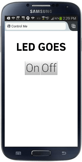
Here is the HTML code for the controller page…
[code language=”html”]
<!DOCTYPE html>
<title>Control Me</title>
<script>
function send(s) {
r=new XMLHttpRequest();
r.open(‘GET’,’/cgi-bin/control.cgi?COMMAND=’+s+’&’+(new Date()).getTime(),false);
r.send(null);
}
</script>
<center>
<H1>LED GOES</H1>
<button onclick=’send(1);’>On</button>
<button onclick=’send(0);’>Off</button>
<hr>
</center>
[/code]
You can see that the on button has a send(“1”) and the off button has a send(“0”) wired to it. There is nothing special about the values “1” and “0” – whatever is in the send is what gets eventually to our code running on the Arduino.
Now let’s look at that code running on the Arduino side that receives these commands. Check out the loop function in BlinkMe.c…
[code language=”c”]
…
void processCommand( const char *commandString ) {
// Use the first byte to specifiy action…
switch (commandString[0]) {
case ‘0’:
pinMode( LED_PIN, OUTPUT );
digitalWrite( LED_PIN , LOW ); // Turn off the LED
break;
case ‘1’:
digitalWrite( LED_PIN , HIGH ); // Turn on the LED
break;
}
}
…
[/code]
We are checking the first character of the received command and if it is “1” then we turn on the LED and if it is “0” then we turn off the LED. Note that we are ignoring anything else that might be received after the “1” or “0”, and we fail gracefully if there is anything that is not a “1” or a “0”. This is important because people could theoretically send anything they wanted to the Yun over the open link and we want to make sure they that can’t cause any problems.
If you can’t wait to put this out in public, make sure you change the root password on the Yun to something besides the default of “arduino” or else someone can pwn your setup. To change the password, connect to the Yun over Wifi and pull up the admin pages at http://192.168.240.1/luci.
Tune in next time when we will add a slightly more complicated (and annoying!) feature!
FAQ
Q: Why not use the sketch /www subdirectory to get the HTML files onto the Arduino?
A: This feature seems to require you to have an SD card mounted and then you need to manually execute shell commands to get it to work. Just seemed easier to ECHO the files from an easily downloaded setup sketch. Please let me know if I am missing somewhere here.
Q: Why do you run a second uhttpd server on port 8080?
A: This secondary server does nothing but issue HTTP 302 redirects back to the primary server, which serves the control page. But why do we need this? Because we don’t know what page the phone is going to ask for, so we must be ready to serve a redirect for any page (including root). I could not find a good way to have a single uhttpd server that could both serve normal pages and also serve a CGI script for any other requested but not found pages.
Q: How did you get the control screen to pop up automatically upon Wifi connection?
A: This is easy for iPhones- as long as you give them a redirect when they ask for their magic “phone home” page, they will generate the login popup. Android phones seem to be more picky – none of the Android phones I tried will generate a popup if the redirect target webserver is on the same subnet as the phone itself. Instead the phone sits there and eventually says “internet connection is unstable”. To get around this, I use a DNSMASQ alias to send all web requests to the made-up address 1.1.1.1 just to trick them. I have never seen this documented before and even tried to find it in the Android isCaptivePortal source, but couldn’t. If you know where this behavior comes from, please let me know!
Q: Why are the buttons so tiny on my phone?
A: To keep things simple, I am using just generic HTML in these examples. In future episodes, we will use CSS to make the buttons look very nice on phones.
Q: Can I use this on other OpenWRT devices besides the Yun?
A: Sure! You can download a shell script that will directly set everything up here. Then you just have to change the /cgi-bin/control.cgi to communicate with your project how ever it is set up.
Q:Why is there a 300ms delay between when I hit the button on the webpage and when the light comes on?
A: This is caused by the mobile web browser waiting to see if you are going to double-click before sending the button press. We will fix this in later episodes.
Q: Can we do more than just turn an LED on and off?
A: Stay tuned!
Q: Is there any way to send data back from the Arduino to the web control page?
A: Stay tuned!
Q: Is there any way to log visits to the controller web page?
A: Stay tuned!