Save the Earth One Resistor at a Time – External pull-up resistor no longer needed for DS18B20 temp sensor
EXECUTIVE SUMMARY:
Using the updated Arduino 1-Wire library code presented here, you can eliminate the need for an external pull-up resistor for typical small networks of DS18B20 temperature sensors. This should also work with any AVR processor and other types of 1-Wire devices as well. You can download the updated 1-Wire library here…
https://github.com/bigjosh/OneWireNoResistor/archive/master.zip
The mythical “required” external pull-up

From the DS18B20 Data Sheet
If you’ve ever used the ubiquitous (and amazingly useful!) DS18B20 family of 1-Wire temperature sensors, you’ve almost certainly used a 4.7K ohm pull-up resistor as well. Every one of the seemingly endless Arduino DS18B20 tutorials on the web starts with some version of the line “You will not be able to do anything with this senor until you go out and procure yourself a 4.7K ohm resistor”. AdaFruit is even generous enough to include one of these resistors with every DS18B20-based temperature sensor they sell (be it bare, waterproof, or hi-temp) because they know you are going to need it.
I am here to tell you that everything is about to change. If you were banking on your stockpiles of 4.7K ohm resistors to be the one reliable store of value in these uncertain times, you need to rethink your long-term asset preservation strategy because the decade-long run of stable demand for this part is about to plummet. Yes – it is now possible to connect DS18B20 sensors without any external pull-up resistor at all!
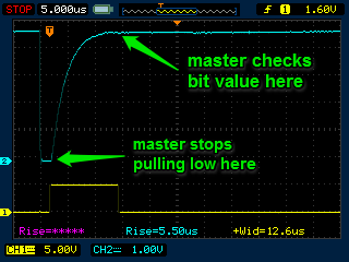
Outrageous claims demand outrageous proof, so let’s start with a brief demo that proves beyond a shadow of a doubt that this is not just a cockamamie theory, but cold hard fact…
Understanding the pull-up
In the time-tested tradition, the 4.7K ohm pull-up resistor is always connected between the power and the bus and holds the bus high unless either the master or one of the salves is actively pulling it down. This is handy because multiple devices can pull the bus low at the same time and nothing bad happens. There is a neat protocol that everyone follows that lets them carry on orderly communication on this shared wire.
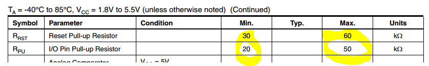
It turns out that the processor in the Arduino has built-in internal pull-ups on the I/O pins that can be enabled via software. These pull-ups can be very handily because they let you, say, connect a switch between a pin and ground. The pull-up will hold the pin at high unless the switch connects it to ground. These internal pull-ups are specified in the Data Sheet as 20K-50K ohms…
While this is a lot more resistance than the 4.7K ohms specified for the 1-Wire pull-ups, we can still make it work for many cases. There real limiting factor here is time – the time it takes for the bus to come back up to a high level after one of the devices is finished pulling it to low.
Without going into too much detail, here is what it looks like when a 1-Wire master reads a bit from a slave (also from the DS18B20 data sheet)…

The master will pull the bus low to tell the slave it is ready to read a bit, and then it will let go of the bus to see what happens. If the slave wants to send a 0, it will signal so by pulling the bus low. If the master sees that the bus is STILL low even after it has let go of it, then it knows that the slave is sending a 0 bit. If the slave wants to send a 1 bit, then it does nothing and just lets the bus get pulled back up to high when the master lets go. The master looks at the bus after it has let go, and if it has returned to high then it knows that the slave sent a 1. Cool, right?
In the case of the slave sending a 0 bit, the pull-up has no effect during the actual bit transmission. We go from the state of the master actively pulling low, to the state of both the master and the slave actively pulling low, to the state of just the slave pulling low. The bus is actively low throughout the entire bit and would be so even with no pull-up at all.
In the case of the 1 bit, we need the pull-up to pull the bus high after the master lets go. This is the moment that the red arrow is pointing to above. The stripped area underneath the arrow is time period where the bus is being pulled from low to high by the pull-up. This does not happen instantly because the pull-up resistor, the devices on the bus, and the wires connecting them all form an RC circuit. The bigger the resistance and the capacitance, the longer it will take for the line to get back up to a high level.
The spec says that in the case of a 0 bit, the slave will pull the bus low within 1us of the master pulling it low, and will hold the bus low for at least 15us after. To be able to tell if the slave was sending a 1 or 0 bit, the master looks at the bus during this time to see if it stayed low (the slave was pulling it low to send a 0 bit), or it returned to high (the slave sent a 1 bit by not doing anything and just letting the bus get pulled back up to high after the master let go).
These protocol constraints limit the size of the pull-up resistor and the capacitance of the system. If it takes the bus longer than 15us to return to high after the beginning of this sequence, then the master will see the bus as low and falsely think that the slave was sending a 0 bit. Since the spec also says that the master must hold the bus low for at least 1us to start the whole process, so we are left with 14us for the pull-up to pull the bus up from low to high.
“1” bit with an external pull-up
The yellow trace at the bottom is a trigger I setup to to show when things happen. The trigger goes high when the master lets go of the bus, and then goes low when the master reads the bus to see if a “0” or “1” bit is present. The blue trace is the bus and you can see a nice steep RC curve where the bus rises after the master lets go. It just makes it back up to 5 volts by the time the master reads it.
So, can the internal 50K Ohm (worst case) internal pull-up do the job? Well, it all depends on the resistance and capacitance of the devices on the bus and the wires connecting them. It turns out that this is also a limiting factor when using an external 4.7K pull-up, it is just that the smaller pull-up resistor will give you more headroom for higher resistance and capacitance in the network.
There are very helpful documents that give heuristics to determine how many devices, how much wire, and what configurations will work on normal 1-wire networks with external resistors. All these same hints apply to networks driven by internal 50K Ohm pull-ups, you just get less of everything.
Aim low
For everything to work, our pull-up must be able to pull the bus back up to a “1” within 14us. But what is the minim voltage for the master to see a “1” bit?
Since we are using a digital input pin of our AVR to sense the bus, and since we are running with a supply voltage (Vcc) of 5 volts, the datasheet gives the answer here…

Minimum input voltage level for a 1 bit when running at 5 volts
We need at least about 2.6 volts on the I/O pin for it to be seen as a “1”.
Can it work?
It turns out that this is just a classic RC circuit that looks like this….

The larger C1 is, the longer it will take to charge though the 50K ohm pull-up resistor. We need to find the largest value of C1 that will get the bus up to 2.6 volts in less than 14us.
We can use the formula..
Vc = V * (1- e^(-t / R*C))
…to figure out that we can just make it under the wire if C1 is 400pF. Any larger and the bus might be lower than our 2.6 volt threshold at the end of the 14us (you can check my work here).
400pF is not a lot of capacitance. Can it possibly work?
There are 3 main sources of capacitance in 1-wire networks – the nodes (our DS18B20’s), the wires, and the input pin on the master.
The data sheet for the DS18B20 tells us that the data pin has a maximum capacitance of 25pF…

A typical capacitance for twisted pair wire is on the order of 1pF per inch.
The capacitance of an input pin of a microcontroller like our AVR is typically on the order of 20pF.
Because all of these capacitances are in parallel, we can just add them together to find the total capacitance.
So, as long as stay within the parameters of this formula…
( sensor_count * 25pF ) + ( total_length_of_wire * 1pF/inch ) + 20 pF < 400pF
…then it might just work!
But does it actually work in real life?
It really works. 1 meter of wire with 4 sensors works. 10 meters of wire with 1 sensor works. 3 meters of wire with 2 sensors works. Try it.
Practical usefulness
My hunch is that the internal pull-up will be good enough for the vast majority of people using the DS18B20 sensors. The new library is looks the same as the old one to the programmer and will work with or without an external pull-up, so you can use it for all your projects and hopefully save the resistor most of the time.
If you need dozens of sensors dangling from dozens of meters of wires to monitor the core of your breeder reactor for partial melt, then you can splurge the extra $0.02 for a potentially superfluous external pull-up without hurting my feelings.
Note that in cases where the internal pull-up is not strong enough, you will know it because you will not be able to communicate with the sensors, at which point you can simply add an external resistor and it automatically start working (assuming that the external pull-up is strong enough for your network).
Software Implementation
It turns out to be almost trivially easy to enable the internal pull-up in on an AVR digital I/O pin in software. It is also very easy to add the required code to the existing 1-wire library. You can see the changes needed to the original 1-Wire code here…
https://github.com/bigjosh/OneWireNoResistor/commit/ebba80cf61920aef399efa252826b1b59feb6589
The changes are slight – 2 lines added and 2 removed.
The basic idea is to turn on the internal pull-ups anytime the bus is not being actively driven (either high or low) by the master. This even saves a bit of power (about 10 trillion electron-volts per reset pulse!) in the case when the master is actively driving the bus low because it is no longer fighting against the external pull-up.
The resulting new code is backwards compatible with the old code, and will work with or without external pull-up resistors.
While I had the code open, I also added a new function that lets you tell the difference between a shorted bus and a bus that just has no slaves on it. The function is called busFail() and could be useful in debugging failed networks.
You can find the latest Version of the library here…
https://github.com/bigjosh/OneWireNoResistor
Installation Step-By-Step
- Download, install, and run version 1.6.4 or higher of the Arduino IDE.
- Download the DallasTempurature library as a ZIP and install it by choosing “Sketch->Include Library->Add .ZIP Library…”
- Download the OneWireNoResistor library as a ZIP and install it by choosing “Sketch->Include Library->Add .ZIP Library…”
- Open the example program by choosing “File->Examples->OneWire No Resistor->NoPullupTester”.
- Connect a temperature sensor(s) to your Arduino as shown above.
- Run!
FAQ
Q: How can there be enough current going though the 50K Ohm internal pull-up to power parasite devices on the bus?
A: The DS18B20 chips are spec-ed to pull 5uA when idle (IDQ) . This means a voltage drop of only 0.25 volts per slave device. Since we are starting at 5 volts, and the DS18B20 chip is spec-ed to run down to 3 volts (VDD), then we should wost case be able to get up to 8 salves on the bus before the voltage drop across the internal pull-up is the limiting factor.
Q: How about the 1.5mA per slave needed during a temperature conversion or EEPROM write?
A: Despite the dire admonishment on the wiki, the 1-Wire library actively drives the bus high during these power hungry events if there are devices are running on parasite power. This means that the pull-up resistors (internal or external) are irrelevant in these cases. A digital I/O pin is spec-ed to be able to drive 20mA, so you should be able to do a simultaneous temperature conversion with up to a dozen parasite-powered sensors on the bus. In practice, I’ve done even more and it worked fine so the sensors are probably drawing less than the spec-ed 1.5mA maximum current.
Q: Help! I need to add more slaves/wire to my network and I am just not willing to fork over my hard earned money to buy that external resistor unless it is 100% necessary!
A: We still have some tricks up our sleeves to get even more headroom out of our networks. Our limiting factor above was that the “1” bit did not have time to rise all the way up the level where it could be register as a “1” on the digital input pin (about 2.6 volts). Even though there is not enough voltage for a digital I/O pin to see it as a “1” we can clearly see it is rising just by looking at it. If we were to switch over to an analog input pin, well then we could detect rises as small as micro-volts! This would give us much, much more headroom on both internally and externally pulled-up networks. And, it just turns out that the way our AVR chip samples analog pins works out perfectly for this task. There is way too much info to shove in this FAQ answer- but maybe I’ll write a follow-up article with working code if there is enough interest.
Q: Wait, I understand everything about the internal pull-up, but how did you get the the sensor to work directly plugged into the Arduino header?
A: Easy – I just added the following lines of code to the setup() function…
  // This lines just make it so you can plug a DS18B20 directly into
  // digitial pins 8-10.

  digitalWrite( 8 , LOW );
  pinMode( 8  , OUTPUT );
  digitalWrite( 10 , LOW );
  pinMode( 10 , OUTPUT );
These two pins are now driven low and effectively ground, so both the Vcc and the ground of the sensor are now connected to ground even if you plug it in upside down (remember that Vcc can go to ground and not power because we are using parasitic power off the data pin in the middle).
Q: Why the frick don’t you just buy a frickin’ $0.02 resistor you frickin’ cheapskate!
A: I actually have boxes of 4.7K resistors sitting on my shelf. That is not what this is about. I ended up working on this because I was writing instructions for a DS18B20 temperature logger and got stuck on the part about hooking up the pull-up. I looked around the web, and everyone said the external resistor was “required” with no explanation.I bet there are lots and lots of people who have excitedly sat down to build a project with a brand new DS18B20 sensor that they picked up on the way home, only to loose all their momentum when they found out that they need an extra part that they didn’t have. Hopefully now future generations of DS18B20 builders will avoid this frustration.
I am also obsessed with eliminating hardware with clever software wherever possible. Hardware is mater and is therefore you have to manufacture, move, and dispose of each and every hardware part used. None of these these problems apply to software – write it once and and it can be efficiently used infinitely many times in infinitely many places by infinitely many people. And when you dispose of an old piece of code, you have more room than when you started rather than less. We will never run out of room for code landfills. I’d guess that clever software could eliminate about 20% if the matter in most technological objects. Think about a world where every phone, computer, and car was 20% less stuff. Think about the effort required to manufacture all that needless mass, and to transport it around the world, and then to dump it. I am happy to trade some of my time once to repeatedly get rid of the need for a widely used $0.02 resistor!
If you have a spare digital IO pin you can tie two of them together providing two internal pull up resistors (once configured). You still only read and write through one pin, but you will be able to handle more devices without the external resistor. Nice article.
Absolutely! You could even tie 8 pins together and just about match the 5kohms spec’ed for an external resistor.
As long as all the pins were on the same PORT, then there would not even be any performance cost and only a very slight code modification (changing the bit mask).
Thanks!
-josh
After receiving 2 DS18B20 in the mail today, I was disappointed I didn’t have a pull up resistor. I stumbled across this and it worked beautifully for me. Thank you!
Hmm, I get the value 85.00 from my sensor?
I’ve connected them to port 8,9,10, downloaded you version of the OneWire library and the normal dallas one, and done the digital writing in the beginning, my code:
#include
#include
float temperature1;
float temperature2;
OneWire oneWire(9);
DallasTemperature sensors(&oneWire);
void setup() {
digitalWrite( 8 , LOW );
pinMode( 8 , OUTPUT );
digitalWrite( 10 , LOW );
pinMode( 10 , OUTPUT );
Serial.begin(9600);
sensors.begin();
sensors.setResolution(12);
}
void loop() {
sensors.requestTemperatures();
temperature1 = sensors.getTempCByIndex(0);
Serial.println(temperature1);
delay(5000);
// Serial.println(a);
// temp++;
// delay(5000);
}
I just put the exact code that I used up on GitHub here…
https://github.com/bigjosh/OneWireNoResistor/tree/master/OneWire/examples/NoPullupTester
Give that a try and let me know if it still doesn’t work and we will figure it out.
thanks, this is very helpful
I did a quick experiment with this today, using a Leonardo. and an 18B20.
With this code, I was able to use the device without the pullup only by attaching the third pin of the 18B20 to 5V. It worked in that mode with this library, but not with the stock OneWire. When I removed the 5V from the 18B20 it didn’t respond with either library.
I didn’t scope it as I had a 2K resistor sitting around that worked as a pullup.
In my application I have a few other passives so I will keep the 4.7K, but this is an interesting take.
On the standard part, the Vdd pin (pin #3) must be connected to ground when operating from parasite power. There is also a version of the part called the DS18B20-PAR that has the Vdd connected to ground internally, so pin #3 is not connected to anything.
Ah! RTFM!
I’ve always been using them with all three pins dutifully connected. This was my first attempt at reducing the connections. Very cool.
Now for your next trick, figure out how to reduce the passives count when using a split core current sensor….
For further data, the Sparkfun waterproof sensor (https://www.sparkfun.com/products/11050) has been working for me for a few days with the third wire unconnected but using a pullup on the data line. I’m not sure if internally it uses the -PAR part, but I’m guessing not or the third wire would be omitted.
I did notice though that over time it reverted to a higher precision than I originally set. So I suspect it self-reset once, but it returned and continued to report. I’ll hazard a guess that this configuration is not recommended.
I will build another prototype shortly and see if it will work using your code and no pullup.
I have errors with the NoPullupTester during compilation of the code:
NoPullupTester.ino: In function ‘void loop()’:
NoPullupTester.ino:50:17: error: ‘class DallasTemperature’ has no member named ‘reset’
NoPullupTester.ino:56:19: error: ‘class DallasTemperature’ has no member named ‘busFail’
‘class DallasTemperature’ has no member named ‘reset’
I have latest IDE 1.6.4, DallasTemperature (3.7.2) and your OneWire libraries via GitHub.
Where is the problem?
Ok, I just updated the package to be compatible with the new Arduino library manager stuff. It should now be very easy to get the example program up and running. Check out the new step-by-step instructions at the bottom of the post and let me know if you run into any problems. It might make sense to delete any old installs of either the DallasTempurature or OneWireNoResistor folders in your Arduino libraries directory first to avoid any conflicts.
Quicker solution just for this specific issue: Try commenting out the “#define BUSFAIL” line at the top of NoPullupTester.
Nice post. I happened to test the parasitic capacitance of AVR pins, and it is even lower than your stated 20pf.
http://nerdralph.blogspot.ca/2015/10/parasitic-capacitance-of-avr-mcu-pins.html
Interesting. Do you also need to take into account the ~1 megaohm resistor from the probe to ground inside the scope? This would seem to discharge the pin while you were trying to charge it, making the charge time longer and the the perceived capacitance higher.
I had my probes on 10x mode which is 10MOhm, so it can be ignored given my measurements are at best accurate to within 10%.
Just tested out your fork; it works fine.
I made a small change to setup so the pin above and below the onewire bus pin is grounded instead of pins 8 & 10:
digitalWrite( ONE_WIRE_BUS-1 , LOW );
pinMode( ONE_WIRE_BUS-1 , OUTPUT );
digitalWrite( ONE_WIRE_BUS+1 , LOW );
pinMode( ONE_WIRE_BUS+1 , OUTPUT );
Technically you don’t even need the digitalWrite lines, since the reset state of all port pins is 0 (low).
I also noticed the following (line 13) from the example is unused code:
#define TEMPERATURE_PRECISION 9
Thank you!
Hey,
really cool tutorial. Helped me to set up my DS18b20 without having the 4.7k resistor. I get data but my room is definetely not 80 fahrenheit…is my sensor broken?
Does the reading go up if you warm the sensor by holding it between your fingers? Does it go down if you lick it and blow on it?
Yes, that works without a problem. I tried it with longer and shorter cables, with parasite power and without. lowest i can get is about 76.5 fahrenheit. After starting, the data shows decreasing values (e.g. it starts at 78.0 and goes down to 76.5 in about 5 minutes) then it stays at 76.5…
Any idea?
Best regards!
What temp is your room? Is it possible that the reading is correct? Maybe try putting the sensor into a glass of ice water and seeing what reading that produces?
Fabulous..!!
I’m a total novice to electronics, so most of the detail was well over my head. However, I did know about the concept of internal pull-ups. I got a bunch of temp sensors today and dutifully started to solder on the pins. Then I started to look into how to wire them up. Like I said, I’m a novice … :-) Oh, I was very unimpressed to find I needed an additional resistor. After some rummaging I found said resistor, wired it in, and life was good. Temp sensor stuffed under armpit and voila, 37 degrees. Happy days.
Then I thought, “hang on, what about the internal pull-up – surely I don’t need that bloody resistor messing up my wiring?” (Mmm, for an explanation of ‘novice’, think deeply about the comment I just made) Anyway I Googled “DS18B20 wiring input_pullup”, and guess who was the first on the list.
Everything works beautifully. Plus the wiring (for a simple sensor application) is far, far, far, more elegant.
It has been a pleasure – Well done you!!
Noob question…When using the water-proof probe version, which color wires (black, red, yellow) go to which pins (8, 9, 10)? Since I’m not using the power and ground spots on the board I’m a little lost. Thanks!
Typically red and black would go to ground, and yellow (or sometimes it is white) to data.
If you are suing the NoPullupTester sketch on an Arduino Uno, that would translate to white and black wires to Arduino digital pins 8 and 10, and the yellow wire to digital pin 9. Note that the red and white wires could just as easily be attached to any of the Arduino’s “GND” pins as well.
Ive been using your work for some time now, a great example of intelligent codding.
Thanks
P.S The lib wont work with a ESP8266,
I really appreciate your work! Exactly what I need!
These words really hit me:
“excitedly sat down to build a project with a brand new DS18B20 sensor that they picked up on the way home, only to loose all their momentum when they found out that they need an extra part that they didn’t have”
Thank you for your time!
Only know because it has happened to me so many times.. :)
Can you comment on using 3.3V GPIOs, please? I tried your code with the ESP8266 and it worked on some boards and not on others. And strangely I encountered the situation when the temperatue readings were continously 5 degrees too high.
The DS18B20 can run off of 3 volts, so as long as the wires are not too long then that should not be a problem. The code in this article, however, is very specific to the AVR processor on Arduino boards, and I would not expect it to work on ESP8266 which uses a completely different processor with different IO pin characteristics. While it would probably be possible to use this technique to have an ESP8266 to drive a DS18B20 with internal pullups, you would likely have to start over and write code specifically for that processor.
If your using a NodeMCU [ESP-board], then digital pin D3 already has a pull up on the board that works with the temperature probe. Other breakout boards may have one on a digital pin.
Same goes for a Wemos. D3 is the pin to use. You can configure D1 and D2 as ground (8 and 10 in the example above) if you want to put the three “legs” in three pins next to each other as the video shows.
Just remember that the modded OneWire lib in this article can’t be used with esp, you have to do the exact same mods (+2, -2 lines) in the official latest version of OneWire (github) that supports esp8266.
Sorry D1 and D2 cant be used exactly as I said, the middle one is data.
I was using jump wires :)
D2 and D4 would be better. Or just wire them to ground.
I can confirm it is working on a Nodemcu without the pullup 4.7k. I use 3.3V.
I wire the data line from the sensor to D4 pin and it works perfectly fine, the temperature read is comparable to my others thermometers.
The only result I get is
PARASITE=OFF,Count=0
Did you using the example code and attaching your DS18B20 directly to the Arduino without any wires first to test? If that works, then we can walk though small changes towards your ending setup and see which step makes things break.
I am having the same issue. The Serial Monitor is only printing “Parasite:OFF Count:0”. I only have the wired waterproof sensors, so I can’t plug in the sensor directly.
According to my experiments, without external resistor in parasite power mode the bus (library) does not select sensors with activated alarms. In that case I had to use an external pullup resistor to detect the alarms. What about your experience?
Just recently started working with DS18B20 sensors, this was very interesting. I already bought a ton of 4.7k ohm resistors, but good to know for the future, I’ll have to try it!
I’ve made the proposed change and it worked first time on a 50m long unshielded cable. It wasn’t working before.
GREAT idea and thank you very much for sharing it.
Hi
Thanks for a nice article. However, when I follow it, my Arduino UNO R3 does not recognise the DS18B20 (waterproof model with three wires, approx. 50cm wire), i.e., the Serial Monitor outputs “Parasite:OFF Count:0”. I have tried with other DS18B20 waterproof sensors with no luck. The same hardware works with a pull-up resistor.
I have connected it with the red wire to 5v, black to Gnd, and yellow to Data (pin 9).
I have also tried without the 5v, as you demonstrate in the video. Still no luck.
Any input on this would be much appreciated, as I am in a remote area and need to set up temperature loggers (and I’ve forgotten enough pull-up resistors…)
Thanks in advance!
SOLVED – problem was that I had not removed the old oneWire library. Once properly replaced with your modified library, it worked.
Thanks a lot for sharing.
thank you. saved my butt
Hi,
Looks like you have a very large measurement differences on the video example.
Pull-up reading was 78,8*F, non pull-up was 79,7*F just after removing the resistor. Can you comment on that?
Then the probes measured 76,1 and 79,7 … is it a matter of ds18b20 accuracy?
Cheers!
The sensors have small thermal mass, so they easily heat up a couple of degrees when handled by my warm fingers!
If this was a data corruption issue, then it would be very unlikely that you’d get in-accurate readings. You’d get more likely get nothing since the I2C protocol is pretty intolerant of errors, especially with a multi-step process like these sensors need to be discovered and give a response.
Hello, This is a great tool to save space on boards, and solve the problems I have.
I don’t know if this is still updated, but I have 2 of these sensors with cable lengths of about a meter. I can plug each one in individually and the noresistor program works, but when I try to plug them in together, count goes from 1, back to 0. Is the cable length the issue here?
Thank you!
Solution, it was the cable length. I cut one to about 10cm, and everything works hunky dory now, cheers!
One weird idea would be to speed up the return to high by sending a short high pulse through the MCU pin. Just like in the Ognite project where you do not use a resistor but you use a short controlled pulse to limit the current.
When the client sends a 0 then it would be two transistors driving against each other but as long the pulse is short and only fills the capacity of the line with electrons then it can’t ruin them with overcurrent. Or at least I hope :-).
The problem is the asimmetry: pulling towards 0 is fast, pulling towards high is slow. Why not help the pull towards high a bit by an active pull?
Hmmm…. it might be possible to occasionally inject a short pulse of current into the bus and see what the response is. My guess is that it would be hard to interpret the reaction unless you know how far away the node that is (was) pulling the line low is, the total length of the bus, and the capacitance of the bus. Remember that the bus is actually a , and a very short pulse could be short enough that reflections start to matter. Or maybe you could actually look for the reflection and use that to detect if the line was still actively connected to ground?
But if you really want to get data off the line more quickly, I think possibly simpler to read the line voltage with the analog to digital converter and potentially see the pattern of the beginning of the voltage rise before it gets to the digital threshold.
Hello i like the idea but didnt upload your library, i just open the onewire.cpp with notepad and changed pinMode(pin, INPUT); to pinMode(pin, INPUT_PULLUP);. Now it is working like a charm without any external resistor. I am using esp8266 maybe the other arduino boards are different.
I know a lot of people have been looking for a solution that works on ESP8266! Maybe this will also work on ESP32? Thanks!
OneWire oneWire(ONE_WIRE_BUS);
pinMode(ONE_WIRE_BUS, INPUT_PULLUP);
-ie just set the pin being used to input_pullup after initialising oneWire.
Works for me.
Really? Did you test with an actual Arduino UNO and an actual DS? Did you check that you got back actual (not all 0’s) data?
That should not work. If you look at the OneWire source, you’ll see that it blindly resets both the pin mode and PORT value several times on each and every bit…
// Read a bit. Port and bit is used to cut lookup time and provide

// more certain timing.

//

uint8_t OneWire::read_bit(void)

{

	IO_REG_TYPE mask IO_REG_MASK_ATTR = bitmask;

	volatile IO_REG_TYPE *reg IO_REG_BASE_ATTR = baseReg;

	uint8_t r;
noInterrupts();
DIRECT_MODE_OUTPUT(reg, mask);
DIRECT_WRITE_LOW(reg, mask);
delayMicroseconds(3);
DIRECT_MODE_INPUT(reg, mask); // let pin float, pull up will raise
delayMicroseconds(10);
r = DIRECT_READ(reg, mask);
interrupts();
delayMicroseconds(53);
return r;
}
It does not do anything to check what the pin mode was before or try to restore it after, so whatever `pinMode()` setting that may have been set is immediately lost forever.
Maybe you are using some other platform other than AVR that has independent internal pull-ups?
Until I added that line, I was getting -127 as the temperature from the one DS18B20, ie no reading. Adding that line to my code, it works.
OneWire library is version 2.3.6.
Platform is a bare ESP8266 on a plug-on carrier. I plan to wire one up with a battery and put it in my new freezer top drawer, sending temperatures to my local server every 10 minutes. (Freezer has a plastic top.) I’m using deep-sleep code.
I figure if I solder wires to the top of the ESP8266, it can still be plugged into the carrier for reprogramming. Easier than adding a connector and resistors/switches to plug in an external USB-serial adapter.
Battery is LiPo, via a diode to drop the volts a bit.
> Platform is a bare ESP8266
Yes, many platforms like ESP have independent pin pull-ups, but the standard Arduino AVR platform this post is about does not so you have to do a bit of extra work.
The other thing I tried which also works, is setting a different IO pin to pullup and connecting it to the one-wire pin. -Without my extra line of code.
> The other thing I tried which also works, is setting a different IO pin to pullup and connecting it to the one-wire pin.
Yes, if you have extra pins that have pull-ups on them then you can always use these. You can even use multiple pins ganged together to get faster bandwidth. But when tying pins together you always have to be very careful not to ever accidentally drive more than one of the connected pins at a time or you could burn them out!
Hey there fellows. Just for the record.
I plugged in my brand new shiny waterproof-encased sensor. I am NOT trained in electronics and when I read that the thing needed a resistor I was like WT…but after having found this site, and understanding everything, gave it a try and the result was EXCELLENT. Josh your code worked, and albeit my sensor is reading with the “Parasite” mode in “Off”, the readings are quite close to the ones with my external trustable temperature gauge. So that means it is effectively working.
Thanks dude, you saved me big time and hassle looking for a stoopid resistor. I will follow your smart software to minimize hardware creed from now on. Keep coding. The world needs you.
This is a very case I had hoped this code would be useful for! :)
Thank you! Worked immediately in 2023
Hello there. It´s me again, now with a Wemos D1 R1. It´s not working, and I´m looking for the way to make it work. If anyone out there has done it please let us know. Thanks!
There are internal pull-ups on some of the pins of the Wemos D1 so it is possible to get something like this working, but you would likely need to do some work to change the code to work with this board.
On an ESP32 (ESP32-SOLO-1) I had to change line 149 of the default OneWire library from “pinMode(pin, INPUT)” to “pinMode(pin, INPUT_PULLUP)” and it works now, without a resistor.