The Perfect Pulse- generating precise one-shots on AVR8

It is possible to generate one-shot pulses on an AVR that…
- Are as narrow as a single clock cycle (63 nanoseconds!)
- Are precise to a single clock cycle
- Will run to correct completion no matter what else the processor is doing 1
- Do not require you to turn off interrupts at all (!)
- Do not require any assembly code
These pulses are generated in pure hardware. They require a couple of instructions of interruptible code to fire. Once fired, they are completely autonomous and depend only on the system clock to run to completion.
Sound cool? Read on!
Update 11/22/2019
The new AVR0 chips have a built-in and well documented single shot mode!

Demo
Here is a handy demo program…
https://github.com/bigjosh/TimerShot/blob/master/TimerShot.ino
This demo is written for an Arduino to make it easy to try, but this technique can work on any AVR8 with a timer module.
Download and run the demo and your Ardunio will start outputting one pulse per second on digital pin 3.
The 1st pulse is 0 cycles long (no pulse),
The 2nd pulse is 1 cycle long (~63ns),
The 3rd pulse is 2 cycles long (~126ns),
…up to a total of 20 pulses, and then will start over.
The output should look like the above animated GIF. The yellow trace is the pulse.
Note that there is no cli() or ATOMIC() anywhere in the code. Interrupts are on the whole time, yet you will never see a stretched pulse because an interrupt happened to come along at just the wrong time. You will also never see jitter because the firing was delayed.
It is like magic!
Usage
TLDR;
To make a pulse, call…
OSP_SET_WIDTH(cycles);
…where cycles is the number of clock cycles wide you want the pulse to be. For example…
OSP_SET_WIDTH( 1000 );
…will output a pulse that is 1000 cycles wide.
More options
Here are the functions and macros you can use to add precise one-shot pulses in your own code…
osp_setup()
osp_setup(cycles)
Setup the timer to generate one-shot signals. Must be called before any of the other functions. Can be called multiple times. You can optionally specify the width of subsequent shots in cycles.
OSP_SET_WIDTH(cycles)
Set the width of any subsequent shots to the specified number of cycles.
OSP_FIRE()
Fire off a shot using the most recently set width.
OSP_SET_AND_FIRE(cycles)
Set the width for this and any subsequent shots to cycles, and then fire a shot. Slightly faster than calling OSP_SET_WIDTH() followed by OSP_FIRE().
OSP_INPROGESS()
Returns true if there is currently a shot in progress.
Width
At any moment, there is a width set and the next shot fired will have that width. Firing a shot does not change the current width setting.
- You can set the each time you fire a shot using
OSP_SET_AND_FIRE(). - If you are going to be firing several shots of the same width in a row, it is slightly faster to set the width with
OSP_SET_WIDTH()once and then callOSP_FIRE()for each shot. - If you know the width of the first shot (and possibly subsequent shots), it is slightly faster to specify the initial width when calling
osp_setup()and then callOSP_FIRE().
Testing for a pulse in progress
You can check if there is currently a pulse being generated with OSP_INPROGRESS(). If it returns 0, then the most recently fired shot has completed. Because of the overhead of executing the OSP_INPROGRESS() macro and code that uses the result, there will always be a few cycles of downtime between fires.
Because they run independently, the end of a one shot can occur while the CPU is in the middle of an instruction. This can cause some jitter when testing for the end of pulses, but you will never have to worry about erroneously seeing the pulse finished while it is still in progress. Check out the animated GIF above to get a feel for how the end-of-pulse test interacts with different pulse lengths (the blue trace goes low when the code detects and acts on OSP_INPROGRESS() going low).
Computing cycles
You can use the F_CPU macro to figure out how many cycles at the defined clock speed. F_CPU is defined by the compiler to be the number of cycles per second, so you could use…
OSP_SET_AND_FIRE( F_CPU / 1000000 );
…to generate a 1us pulse (1us =1/1000000 of a second).
Note that F_CPU assumes you are using a normal clock setup. if you are messing with fuses or otherwise changing the cpu clock settings, then you’ll have to figure out what your new F_CPU should be and redefine it in your code.
Examples
[code lang=C]
osp_setup(1);
OSP_FIRE();
[/code]
Fires a single shot that is 1 cycle long (about 63ns with a 16MHz clock). Note that you do not need to test if a 1 cycle shot completed because just executing the code to check would take many cycles.

[code lang=C]
osp_setup();
OSP_SET_AND_FIRE(10);
while (OSP_INPROGRESS());
OSP_SET_AND_FIRE(20);
while (OSP_INPROGRESS());
OSP_SET_AND_FIRE(30);
[/code]
Fires three shots, of width 10, 20, and 30 cycles each respectively. There will be at least 1 cycle of space between the two shots (in practice it will be at least 10 cycles because that is how long it takes the CPU to evaluate and exit the while.

[code lang=C]
osp_setup();
for (uint8_t i = 1; i < 10; i++) {
OSP_SET_WIDTH(i);
for (uint8_t j=0; j<=i; j++) {
OSP_FIRE();
while (OSP_INPROGRESS());
}
}
[/code]
Fires 1 shot that is 1 cycle long, then 2 shots that are each 2 cycles long, then 3 shots that are each 3 cycles long, and so on up to 10 shots that are each 10 cycles long. There will be at least 1 cycle of space between all the shots.

FAQ
Why not just use a tight loop to bit bang the pulse out?
- You would need to turn off interrupts for the length of the pulse, or risk being interrupted in the middle of a pulse and stretching it unpredictably. Turning interrupts off for the full duration of the pulse could disrupt any interrupt dependent tasks that might need to run. With this one shot technique, firing a shot happens within a single atomic instruction, so you never need to turn off interrupts.
- You are just burning cycles the whole time you are locked in that delay loop. With this technique, once the shot is fired, the processor is free to go off and do whatever it likes. The shot will continue to run in the hardware and end at exactly the right time no matter what code the processor happens to be executing at that time.
- The shortest pulse you can generate with bit banging is 2 cycles.2 With this one-shot technique you can reliably generate a pulse as short as exactly 1 cycle.
- There is no reliable 3 way to do calculated timing loops finer than microseconds in C, so you have to drop to assembly.
- There is no clean and efficient4 way to generate cycle-denominated loops in assembly.
What is the longest pulse you can generate with this technique?
The code here can generate a pulse up to 254 cycles wide, which is about 16 microseconds on at 16Mhz Arduino.
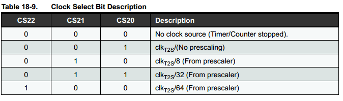
If you need a longer timeout, you can increase the prescaler in Clock Source bits in the TCCR2B register.
Changing the line
[code lang=text]
TCCR2B = _BV(WGM22)| _BV(CS20);
[/code]
to
[code lang=text]
TCCR2B = _BV(WGM22) | _BV(CS22)|_BV(CS21)|_BV(CS20);
[/code]
will change the prescaler to 64, which means that each cycle of the timer will take 64 clock cycles. So, OSP_SET_WIDTH_AND_FIRE(1) will generate a pulse that is about 1 microsecond wide and OSP_SET_WIDTH_AND_FIRE(254) will generate a pulse about 1 millisecond wide.
If you want any longer, you could use the 16 bit Timer1 (the code here uses Timer2 which is only 8 bits). That could give you a pulse width range of about 0-4 seconds, in 64 microsecond steps. Keep in mind that these 4 second long pulses are still actuate to a single clock tick (~62.5ns). Pretty impressive! One complication is that access to the 16 bit counter is not atomic, so you would need to either (1) disable interrupts for about 200ns to fire the shot, or (2) stop the timer, set the counter, and then restart the timer to fire the shot. Maybe I’ll do a full article on this is people want it. UPDATE 10/25/21: Dan correctly points out that these 16-bit timer registers can be accessed automically, making things much easier!
Wait! How the heck does this actually work? I thought the AVR timers were free running!
Stay tuned next week for a full explanation!
- The clock feeding the timer clock much still be running, so you can’t shutdown and you can’t change the clock speed or you’ll mess up the timer. ↩
- …or at least the fastest I can figure is a
sbifollowed by acbi, each of which takes 2 cycles. Is there a faster way I don’t know about? ↩ - You could try the _delay_cycles() built-in, but it is not universally supported (doesn’t work on the OSX version of the Arduino IDE, for example). No matter what, you can never be sure that your code won’t get re-ordered on you and mess up your carefully computed timing. ↩
- There are some complicated tricks to insert some combination of macros based on bits, but these are definitely not clean. You can use the REPT macro to insert a straight series of NOPs, but this is not memory efficient. ↩
Thanks Josh.
I am probably doing it wrong, but if I use:
/*************/
void setup()
{
DDRB |= _BV(4); // Set Digital Pin 12 to output for ossiliscope trigger
osp_setup(320);
}
void loop()
{
OSP_FIRE();
while (OSP_INPROGRESS());
}
/*************/
I get 4 microsecond long pulses. IF I did my arithmetic correctly, they ought to be 20 microseconds. What am I doing wrong?
In any case thanks for your work.
The code here can generate a pulse up to 254 cycles because this is only an 8-bit timer.
320 & 0xff = 64
64 ticks * ~63 ns/tick = ~4us, so what you are seeing is expected.
If you want to generate a pulse that is 320 cycles long, you could try using a 32 step prescaler like this…
/*************/void setup()
{
DDRB |= _BV(4); // Set Digital Pin 12 to output for ossiliscope trigger
osp_setup(10); // 10 clock ticks * 32 prescaler = 320 cycles
TCCR2B = _BV(WGM22) | _BV(CS21)|_BV(CS20); // Prescaler = /32
}
void loop()
{
OSP_FIRE();
while (OSP_INPROGRESS());
}
/*************/
All a prescaler does is divide the clock signal going into the timer, so the timer sees one tick for each 32 clicks of the input clock.
I haven’t tested, but should work. LMK!
Is the reason the 16 bit timer is not atomic with respect to interrupts because it takes two separate reads or writes to access the 16 bit timer registers?
Would you be so kind as to post the code for using a 16 bit timer on an Arduino Mega 2560?
Thanks for a great hack!
It actually looks like access to the 16-bit counter is atomic on the AVR, so everything should work just fine. You will need to transpose all the registers and make everything 16-bit aware. You’ll also need to cross reference the bits to make sure you are selecting the equivalent modes in the 16-bit timer. Finally, if you are using something like Arduino, you’ll need to make sure it is not also trying to use the 16-bit timer (I think it does) and conflict with you. Share your code when you get it working!
hey josh,
I want to generate pulse width ranging from 1ms to 2 second, in a step of 1ms.
can i use ur code directly to generate required pulse. also u said arduino may be using 16bit timer2 and conflict with generated pulse. How to overcome this.
The supplied code only uses an 8-bit time, so the maximum pulse length you could generate with 1ms resolution would be 254ms. You could recode to use the 16-bit timer, which would give you a maximum length of 65.535s. To make the changes, you need to look at the datasheet and follow the same strategy for the registers on the 16 bit timer.
Neat trick, is it possible to use this method to create pulses of width 1500 as well as 1501 microseconds? Using the prescalers results in pulse widths ~8 microseconds apart at that scale. Cheers.
I think this is easy. If you used the 8Mhz RC system clock (or, say, a 16Mhz xtal and /2 system clock prescaler) and a clkio/8 timer prescaler, then you could directly set the pulse width in microseconds. If you used the 16 timer, then just set 1500 for 1500us and 1501 for 1501us.
can pin 8 be used as output instead of pin 3, how would i go about this?
thanks
No go for one-shots on Digital Pin 8. This technique depends on the chip’s hardware timers, so it can only work on pins that are attached to the outputs of the hardware timers. On an Arduino, these pins have a little squiggly next to them which indicates that these pins can do PWM output. Since the PWM uses the same timers, this means any squiggly pin should also me able to do one-shot, although you’d have to edit my program since I’ve hard-coded in pin #3.
Hey, Josh. First of all, this is a fantastic trick. Thank you for sharing. I’m considering various implementations of a one-shot, and this has advantages/disadvantages I’m currently weighing.
I just want to check to make sure my understanding of the jitter in this implementation is correct. If the incoming trigger edge is asynchronous to the AVR’s clock, then there will always be jitter (relative to the trigger) on the starting edge of the output one-shot pulse. This jitter amount would be in the range of zero to one clock period because the asynchronous trigger can randomly occur anywhere between a clock cycle and you need to wait until the next clock to act on it. However, the ending (or trailing edge) should always end at the same time and have no jitter relative to the incoming trigger. Contrasting this to a typical RC one-shot, the starting edge would have a constant propagation delay and only the ending edge will have some amount of jitter due to the slow ramping of the RC circuit crossing thresholds at slightly different instants.
Do I have this understanding correct?
All good questions. I have not though about this in terms of jitter relative to some external event, only relative to internal events (program flow) and the jitter between start and end of the pulse.
If you are reacting to an incoming digital transition on a pin there are likely other sources of jitter to be concerned with. There are buffers and synchronizing logic on the inputs trhat will add jitter. There is also the the actual software way to react to the input – which could be spinning on the input bit or reacting to an interrupt, both of which would add more jittter.
If you goal is simply to make a one-shot fixed-width output pulse in response to an input pulse the the minimum jitter between the input and output, I think there are better ways to do this with some digital hardware. Is this what you are typing to do?
Thanks, Josh!
Yes, my goal is to take an external pulse train and widen the active portion of it. Assume you have a 10% duty cycle pulse train and you need to make it 20% while the leading edges between every input and output pulse line up as much as possible. I understand that there is software overhead, but that is deterministic and can be compensated for. The only randomness I can see would be within the window between clock cycles where the trigger can occur. For simplicity of this exercise, assume the AVR is doing nothing else except performing the one-shot operation on the external event.
Like I mentioned before, if a standard RC-based one shot is used (74LV123, 74HC4538, etc.) the starting edge is nice and clean, but the ending edge can have jitter. Are you familiar with other hardware methods that are able to mitigate or reduce that?
With the AVR there will be jitter in detecting the incoming pulse and then reacting to that in software to start the outgoing pulse. Even if you do nothing but loop while checking the incoming bit there will still be jitter on the input pin buffer, and where the signal happens to hit in your polling loop. The fastest one of these AVRs can practically run is 20Mhz, and I think the tightest that loop can be is 3 cycles.
Depending on how much precision you need, I’d consider a counter driven by stable clock. The jitter on the output pulse width is practically limited by the resolution and jitter on the clock which can be astronomically low if you use something like a OXCO. The jitter between the input pulse rising edge and the start of the output pulse is likely practically limited by the sharpness and drive strength of the input pulse since that will reduce capacitance on the input lines.
What are you miking?
Thanks again for the response, Josh.
OK, it sounds like we’re in agreement then. The leading edge will flop around due to synchronization with the trigger event.
Nothing yet, but I am trying to think of various ways to widen VGA VSYNC and HSYNC pulses which are too short and out of spec. Some equipment triggers off the incorrect edge, so ideally both resultant pulse edges need to be jitter free in relation to their native pulses. It sounds like I need to define what amount of jitter is tolerable and pick a solution that best fits within that number. Your AVR method might still fit within that.
Thank you for the discussion and insight. I appreciate the help. Again, this is a very cool trick.
This all looks very interesting, Josh.
I’m trying to avoid buzzing and occasional juddering on some of 5 or 6 MicroServo 9Gs all driven from an ESP32.
Could you give me some pointers on what, if anything, would need changing for an ESP32? (Although I’m very comfortable with general programming techniques, I’m not at all used to low level register manipulation and timers, so can’t start to guess how to find the differences at this level between various chips!)
Hoping you can help.
Thanks again.
Les
The code presented here is extremely specific to the timers on the ATMEGA chip and so will not work on any other platform. You could not even use the same strategy on the ESP32, much less the same code.
The ESP32 is however a very capable chip with lots of fancy hardware peripherals, so I bet there is some way to coax it into making fixed width pulses, but it would take some digging to figure out. But if all you want to do is generate some servo PWM signals, I’d think the ESP32’s 16-bit Motor PWM interface would be perfect for that.
Thanks for the speedy reply, Josh. Just a pity it isn’t trivial to do this on the ESP.
Hey Josh!
Amazing piece of work.
I was trying to use this for generating a single pulse between 200-500ns(I’m keeping cycles=5) for HVPP on an Arduino Mega2560.
I need the output pulse from high to low and then go back high again. Can you guide me how to do that?
Thanks a lot!
Why not just disable interrupts and bitbang the pulse?
Thanks!
I tried that, but I can reach upto 1kHz frequency via bitbang (checked with a scope). This was my code:
cli();
PORTB |= (1 << PB5); //PB5 is the pulse output pin for my Mega 2560
PORTB &= ~(1<<PB5);
PORTB |= (1 << PB5);
sei();
I need 2kHz at least (for 500ns)
Those commands should each take 2 clock cycles. With a normal Arduino 16Mhz clock, that code should generate a 125ns pulse on
PB5(assumingDDRB5is set to output). Are you changing the clock speed anywhere? Can you send the scope trace?No, I’m not changing the clock speed anywhere.
And sorry, I meant 1 MHz not kHz in the previous comments.
I don’t have access to a scope right now, but if I remember correctly, the pulse was high for 400ns and low for 100ns using the code I posted.
Do you think you can help me with that?
thank you!
If the clock is running at the standard 16MHz speed and you enter the above code with PORTB5=1 and DDRB5=1, then that code should make a 125us low going pulse. If not, then something else is wrong. I’d try the simplest possible program and see what happens. Something like…
[code lang=”CPP”]
void setup() {
DDRB=_BV(5);
PORTB|=_BV(5);
}
void loop() {
delay(1000);
cli()
PORTB &= ~_BV(5);
PORTB|=_BV(5);
sei();
}
[/code]
…and then check the output. It really should be a low going 125us pulse once per second.
Report back with your findings!
Hi Josh,
This looks like a great idea that I could use in my work. Forgive me if I’ve missed this, I’m just beginning with an arduino, but can this type of pulse be triggered from an external input?
I want to get a fast, reliable, pulse out of the arduino a set time (~0.1-1ms) after it receives a TTL signal.
No problem. If you can dedicate the Arduino to just this, then you can disable interrupts and pool on the input pin state. When the input pin chances, then start the timer that generates pulse as above. With this strategy, you can have the pulse start within 1us of the edge of the input signal. If you need the Arduino to do other things while waiting for the pulse and can sacrifice some latency, then you can set up a pin change interrupt on the input pin and start the pulse timer inside the ISR. If done carefully the latency for this strategy can be as low as 2us + (the longest running ISR in the system). On an Arduino typically the ISR that updates the millis() clock is the only other ISR and it can be easily disabled.
Hi Josh, the code and your examples work beautifully except for one thing. When I use the pre-scaler as per your examples it works fine for no pre-scaler and for 32 as per the calculated values. However, for the 64 prescaler it does not work for a cycle of 1 I get a pulse of 63 uS according to my scope, a cycle of 254 = a pulse width of 16.26 mS so each additional cycle adds approx 63 uS. I reckon 1 cycle should be 63 * 64 = 4032 nS or 4 uS.
Have you any suggestions please.
Possible that you need to clear the prescaller before starting the timer?
You’d want to do this while the timer is stopped.
LMK if it works and I’ll update the article to reflect. Thanks!
Interestingly, the STM32 has this functionality built-in and documented…
https://arm-stm.blogspot.com/2015/12/stm32-timer-one-pulse-mode.html
Thanks for this great explanation.
Regarding your comment on
“…one complication is that access to the 16 bit counter is not atomic, so you would need to either (1) disable interrupts for about 200ns to fire the shot, or (2) stop the timer, set the counter, and then restart the timer to fire the shot. ”
I thought that Timer 1 uses a temporary 8 bit register to implement atomic read/write to any of the 16 bit registers. As long as we do not access any of the 16 bit registers from both the main program and IRQ code, do we need to worry about corrupted values?
Yes, the datasheet confirms you are 100% correct and I am wrong!…
*21.3 Accessing 16-bit Timer/Counter Registers*
“When the low byte of a 16-bit register is
written by the CPU, the high byte that is currently stored in TEMP and the low byte being written are both
copied into the 16-bit register in the same clock cycle.”
So that makes things easier. Have you gotten a one-shot working on a 16-bit timer?
“So that makes things easier. Have you gotten a one-shot working on a 16-bit timer?”
Yes, here is the working example https://github.com/dan-corneanu/TimerShot
However, the affirmation regarding the atomicity of the 16 bit read/write operation, holds true only if any of Timer1 16 bit registers are read either from main or from an ISR routines (that are not interruptible).
As soon as you need to read/write any of the 16 bit registers from both main and ISRs, you do need to wrap the code in an ATOMIC_BLOCK. There is only one temporary 8 register shared by all of Time1’s 16 bit registers. This means accessing any of the 16 bit registers in an ISR can interfere with whatever other register access is happening in the main program (even if it is a different register).
Lovely! I think you can even do it without any `ATOMIC` if you use the match flag to check if the timer is in progress? To do this I also think you would need to use the CS bits to start/stop the timer rather than the assignment to `TCNT`. Make sense?
Thanks a lot for this! Needed an ISR to run 5ms after the rising edge of an external pulse and made it work thanks to your code, by using the Timer2 overflow interrupt.
Btw, for the ATmega328(P), which most of the people here probably use, it’s possible to use a prescaler of up to 1024, which will allow up to ~16ms pulses on the 8-bit timer at 16MHz clock. Don’t know if this works on other µCs in the series, but it’s shown in the table in the datasheet that only covers the ATmega328p.
The higher prescalers are as follows:
CSx[2:0]
101: /128
110: /256
111: /1024
Replace ‘x’ with your timer number of choice.