AVR Timer-based One Shot Explained
Last time, we made one-shot pulses using the AVR’s built in hardware timer module. Today we are going to dive deep into the datasheets to see how this technique is able to coax the normally free-running timer into generating a single pulse. Along the way, we will learn about the low level rules that govern the operation of the timer, and use a trick or two to get around those rules. Read on!…
A Simple Timer
The AVR Timer hardware has lots of modes. For this technique we will be using Fast PWM mode 7…

…which follows these fundamental waveform generation rules (excerpted from the data sheet)…
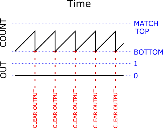
- The counter counts from BOTTOM to TOP then restarts from BOTTOM.
- The output is set when the counter equals MATCH.
- The output is cleared at BOTTOM.
That’s it. Seems straight forward, but with such simple rules how are we going to be able to find a loophole to drive our pulse train though?
The Way Things Are Meant To Be
In normal operation, these simple rules generate a nice repeating waveform like this…

Moving the MATCH closer to TOP gives us less “on” time in our repeating square wave, while moving MATCH closer to BOTTOM give us more “on” time.
The Out Of Bounds Match
What happens if we mix things up and set MATCH to be higher than TOP? It sounds like crazy talk, but these are all just numbers inside a chip and we can set the numbers to whatever the hell we want. The chip will continue to follow its rules no matter what numbers we shove in there.
With MATCH higher than TOP, the counter will follow its rule and reset back to BOTTOM every time it hits TOP, but it will never hit MATCH. It will also still follow its rule and clear the output each time it resets back to bottom, but the output is already clear so it just stays clear. Because it never makes it up to MATCH, the output will never get set. The output will stay low forever…
Upsetting The Pattern
Well, that is not very useful. But while this futile Timer-to-nowhere is impotently counting away, what if we throw a monkey wrench in and directly set the counter to a value that is higher than TOP but lower than MATCH? The counter will continue following the rules and dutifully keep counting up from where ever we set it. It will eventually hit MATCH, and when it does it will set the output just like it is supposed to according to the rules…
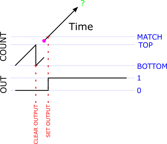
(The purple dot shows the moment we manually set the counter to a value between TOP and MATCH)
We are half way there! We have figured out how to at least make the beginning of a pulse, now we just have to come up with a good way to end it.
Counter To Nowhere?
It looks like the counter is just going to keep counting up and up forever and never hit MATCH or TOP or anything else except infinity. Luckily, the counter is just a register and registers are just composed of a bunch of bits – 8 bits in this case. The largest binary number you can hold in 8 bits is 11111111 (that’s 255 in decimal). The data sheet calls this number MAX, and if you increment MAX by 1, you end up at 00000000 (that’s zero). It is called overflow or rollover. Normally overflowing a register is bad, but in this case it is very nice. It takes us shoots-and-ladders-style right back down to BOTTOM, which is a good place for us to be. Remember that according to the rules, the output is cleared whenever we hit BOTTOM, so we get this…
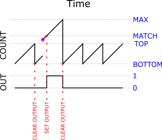
(Again, the purple dot shows the moment we manually set the counter to a value between TOP and MATCH)
Look at that! We have a one shot pulse! Sweet!
Total Control
If you look carefully at moment where we hit MATCH and set the output, you’ll notice that by moving MATCH closer MAX, we also make the width of the pulse shorter…
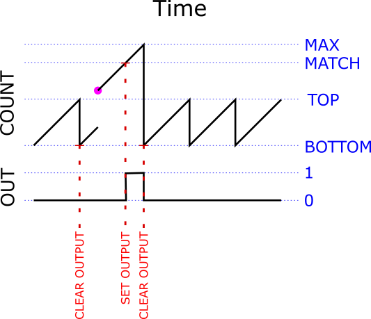
Moving MATCH away from MAX similarly makes our pulse wider. So we can precisely control the width of our pulse by carefully picking the value we give MATCH.
The Big Picture
Our pulse generation strategy just boils down to…
- Set TOP lower than MATCH. Now the Timer is free-running, but constantly outputting a 0.
- Set MATCH to any value we want. Picking a MATCH that is close to MAX makes a shorter pulse, farther away makes a longer one. As long as we set MATCH higher than TOP, then the counter will never reach it on its own so we can modify MATCH any time we want and it will not effect the output.
- When are ready to actually fire the pulse, we jump in and manually assign a value to the counter that is greater than TOP and less than MATCH.
Once we assign our value to the counter, the trigger has been pulled and everything proceeds on autopilot and with perfect lock-step timing….
- The counter will dutifully count up until it hits MATCH, which will set the output- making the rising edge of our pulse.
- It will continue to count up until it hits MAX, at which time it will roll over back to zero (which is BOTTOM).
- Hitting BOTTOM will clear the output- making the falling edge of our complete pulse!
- After it rolls back to BOTTOM, it will get stuck back into an infinite and futile BOTTOM to TOP loop. The output will patiently stay low until we call upon our one-shot again.
Note that to trigger additional one-shots that have the same width as the last one, we need only assign a value between TOP and MATCH to the counter. This can be a very fast and simple operation – as short as a single cycle.
All or None, But Never In-between
One really important thing to notice here is that we can interrupt the above steps any place we want, and in no case will we cause an incorrect pulse to be generated. Try it. Nothing is ever output until the instant when we manually set the counter in step #3 and once we do we do set that counter, then the pulse is out of the gate and will keep running until it is done. Once it is done, it will stay done until we do something else. There is no moment where we started triggering a pulse and haven’t finished yet. It is at every moment either not started, started, or finished (which is really not started for the next pulse)- the pulse trigger is atomic. This is really, really cool and what makes this technique magical.
Technicalities
That is really all there is to it, but there are a few complications to consider…
- The lower we set TOP, the more room we have to move MATCH away from MAX and make wider pulses. If we move TOP all the way down to be equal to BOTTOM, then the counter will be stuck at zero all the time- it reaches TOP on every tick and gets reset back to BOTTOM on every tick. Since we can set MATCH to any value higher than TOP, this gives us almost a full scale (254 possible steps) in which to move our MATCH around in.
- The closer we set the counter to MATCH when we initiate the pulse firing sequence, the less time we will need to wait before the counter hits MATCH and actually starts outputting our pulse. It seems like if we started the counter at MATCH, then the pulse would start instantly. Alas, this doesn’t work because the Timer has a special rule that tells it to ignore any match that happens on the tick after we change MATCH1. This is not much of a problem, we can just set the counter to 1 less than MATCH and the output will get set on the next tick. We can be patient and wait the extra tick, especially since it is a very brief wait (62ns at 16MHz) and always the same. We do loose one more step, making our pulse width range now limited to 0-253 ticks.
- Any time we write a new value to MATCH, our change is buffered and does not actually take effect until the next time we reach BOTTOM2. This could be very inconvenient, except for the lucky fact that by setting TOP to BOTTOM (in complication #1) we actually make it so that we hit BOTTOM (and reload the buffered value into MATCH) on every tick while we are idle and waiting to start the next pulse. That was easy!
- Notice that the only way that the counter could be higher than MATCH is if we manually set it there, which means that if the counter is not 0 then we must have started a pulse. Since the counter gets set back to 0 when the pulse is finished, we can easily and atomically test to see if there is a pulse in progress simply by checking to see if the counter is greater than 0.
Code Key
Here are the actual register names for all these values we have been talking about…
| Value | Register name |
|---|---|
| counter | TCNT2 |
| TOP | OCR2A |
| MATCH | OCR2B |
You should now be able to read the code and it should make perfect sense.
Take Home Message
While 20 years from now you might not care about the intricacies of the internal operations of the 8-bit timer modules on Atmel AVR processors, hopefully this journey has shown you that…
- No matter how complicated the high level description of some piece of computing machinery is, if you look deep enough you will find that its operation is governed by a finite list of simple rules, and…
- The device does not understand those rules, it blindly follows them and applies them to the inputs even if you give it inputs that might not make sense in the context of the high level description of what those rules are supposed to do, and…
- If you know and understand the rules, it is often possible to craft otherwise inappropriate inputs to cause the device to perform some useful operation that is was not designed for.
- From the datasheet: “All CPU write operations to the TCNT2 Register will block any compare match that occurs in the next timer clock cycle, even when the timer is stopped.” ↩
- From the datasheet: “The OCR2x Register is double buffered when using any of the Pulse Width Modulation (PWM) modes. The double buffering synchronizes the update of the OCR2x Compare Register to either top or bottom of the counting sequence.” ↩
thank you Josh. I have used your code to increase the reliability of my electrogalvanic stimulator: https://www.youtube.com/watch?v=j3t3TejWxOI . It may also find application in some transcranial magnetic stimulator (TMS) research
hi Josh
I wish this existed when I had to figure out precise timing for my metronome :D
fantastic resource, really.
I’m gonna see if I can implement some of this knowledge in the future.
thank you for sharing.
:)
Hi Josh, did you ever take a good look at using the 16 bit timer? I have transposed your code, but I’m struggling a bit to get it to work properly. If you have any thoughts, I’d appreciate them.
Thanks!
I looked over the registers and did not see any obvious blocking problems, but I have not tried to actually write the code. One thing to keep in mind is that the access to the 16-bit timer registers is atomic on AVR though a temp register, so this makes things easier.
You are able to set a LOW-HIGH pulse of any width with this trick.
How would you apply this to ws2812 timings?
… I see manually launching each bit as a pulse encoding the low of the previous pulse:
___- zero
___– one
have the ws2812 code do a sleep loop for the whole cycle-1, clear interrupts, and check if the counter is not cleared, else abort transmission, then wait for end of cycle, set next bit, set interrupts?
That way a long interrupt just glitches a refresh but does not corrupt the display?
I have not played with avr timers yet, but I wonder if we can reverse the logic to set a HIGH-LOW pulse. Either reverse the pin level, or raise the BOTTOM value to non zero.
This has the benefit of telling us on a read if we are in a range [1..2] when we can force the next bit out. You can set the LOW duration to max of ws2812 and with a cmp decide if the interrupt corrupted your display (past 2 counter == BOTTOM), yet allow you to preempt deterministically the current cycle to push the next bit…
-__1_______2
—_1________2
Yes! This is exactly why I started on this path. It turns out that it works, but it is only of limited usefulness. If the interrupt comes in the middle of a pixel, then that pixel will get reset with incomplete color info and change to a corrupted color. To avoid this, you need to disable interrupts for the full 24 bits of each pixel.
Note that the longer your string, and the more frequent your interrupts then the more chance that a string update will get aborted and so the more stale the far end of the string will be.
I think it’s worth trying and putting into a lib as an alternative. It also allows 4mhz drivers to work reliably. can the bottom value be controlled to simplify pulse control?
This would give a good reason to fix the time interrupt code.
Hi Josh:
This is an excellent article and I am interested in using it for a project I am working on, however, when I loaded this into my ATMEGA2560 board I was unable to get it to run. Is there an issue running this on the larger processors? Thanks for your help.
Should be no problem – there are plenty of timers (5!) available on that chip and they all seem to have the required functionality. Are you sure you are looking for the output on the pin corresponding to the timer you are using?
Thanks for the quick reply Josh. I loaded the program exactly as written into my ATMEGA2560 board. It compiled correctly and gave no errors, however, I am not seeing the expected pulse signal on the specified pin, or any pin for that matter. Did I miss something?
Ok, I think I’ve got it figured out. I’ve transposed your original code to use a 16-bit timer (timer-3), and also to run on an ATMEGA 2560 platform. For those interested, here is the code:
#include
#include
#define OSP_SET_WIDTH(cycles) (OCR3B = 0xffff-(cycles-1))
// Setup the one-shot pulse generator and initialize with a pulse width that is (cycles) clock counts long
void osp_setup(uint16_t cycles) {
TCCR3B = 0; // Halt counter by setting clock select bits to 0 (No clock source).
// This keeps anyhting from happeneing while we get set up
TCNT3 = 0x0000; // Start counting at bottom.
OCR3A = 0; // Set TOP to 0. This effectively keeps us from counting becuase the counter just keeps reseting back to 0.
// We break out of this by manually setting the TCNT higher than 0, in which case it will count all the way up to MAX
// and then overflow back to 0 and get locked up again.
OSP_SET_WIDTH(cycles); // This also makes new OCR values get loaded from the buffer on every clock cycle.
TCCR3A = (1<<COM3B0) | (1<<COM3B1) | (1<<WGM30) | (1<<WGM31); // OC3B=Set on Match, clear on BOTTOM. Mode 15 Fast PWM.
TCCR3B = (1<<WGM32) | (1<<WGM33) | (1<<CS30); // Start counting now. Mode 15 Fast PWM.
DDRE = (1 <0)
// Fire a one-shot pusle with the specififed width.
// Order of operations in calculating m must avoid overflow of the unint8_t.
// TCNT2 starts one count lower than the match value becuase the chip will block any compare on the cycle after setting a TCNT.
#define OSP_SET_AND_FIRE(cycles) {uint16_t m=0xffff-(cycles-1); OCR3B=m; TCNT3 = m-1;}
void setup()
{
osp_setup();
}
void loop()
{
// Step though 0-19 cycle long pulses for demo purposes
for (uint16_t o = 0; o < 20; o++) {
OSP_SET_AND_FIRE(o);
while (OSP_INPROGRESS()); // This just shows how you would wait if necessary – not nessisary in this application.
delay(1000); // Wait a sec to let the audience clap
}
}
HI Josh & Hahn
I hope you will be fine.
Thank you both for tricks
Hahn! I have tried your code, it’s working fine. I have a few questions.
1- Crystal oscillator on my ATMega2560 is of 12 MHz which means clock time-period / instruction cycle of ~84ns. But your code is generating a 63ns wide pulse. Is it due to PWM?
2- i wasn’t able to get output until i added osp_setup(); in loop();
although called in setup(); already, i have to call it again in loop(); is it an error in your code or my loop(); was coded wrong before adding osp_setup();
my loop() is
void loop()
{
osp_setup(); // after adding this line, i got output at pin 11 of MEGA2560
uint16_t o = 5;
OSP_SET_WIDTH(o);
OSP_FIRE();
}
This code is really bare metal and written specifically for the ATMEGA328 chip. It will not necessarily work on other chips with different timer designs and registers.
Just a quick look at the ATMEGA2560 datasheet shows that it uses a different timer design from the ATMEGA328…
While it is possible that you could use the technique here to make similar pulses on the 2560, you would have to go though each register and make sure it does what is expected for the pulse generation code.
hanks for your reply Josh!
I ,actually, used your methodology, sorry for saying “code” but still my 1st question is same.
Regarding 2nd question,i figured out the problem in my coding problem.
anyways, i need your help in small project, i am developing a systems which needs 3 trigger signals on 3 different input pins. Time difference or delay b/w two trigger signal should be less than 100ns and programmable (say delay can be changed from 1clock cycle’s time to 1 ms ) Is it possible to generate these trigger signals using your methodology?
On pressing a pushbuttion, these 3 trigger pulses should be generated
This technique is not well suited for three pins since you’d have to sync multiple timers. Maybe possible, but lots of work.
If you can live without interrupts for up to 1ms (which is not too long to live without interrupts!) then you can likely do exactly what you want by turning them off and then carefully bit twiddling in assembly. You should be able to get your 1 cycle toggle time by using OUT instructions with pre-loaded registers. You will also need to special case out the shortest delays to use straight though code, and then use loops when the delay is longer than the loop overhead. You can probably use __delay_us() macro to avoid having to do the cycle counting yourself.
After a struggle I’ve gotten your code modded by Chris Hahn to work on Timer 1B for long pulses when using the prescaler. Turns out that there must be at least one clock pulse output from the prescaler between programming the OCR1B register and the TCNT1 register. I’ve added a
OSP_SET_AND_FIRE_LONG(cycles) macro, a bunch of prescaler values and associated time wasters using delayMicroseconds(). Please let me know how I can attach the sample code. Thanks, Nevell
Here’s working code and program examples for Timer 1A and Timer 1B. It works on both ‘328P boards like the Uno and 2560 boards with one small comment change. The prescaler is supported to create pulses up to 4+ seconds length.
I used Mode14 rather than 15 to free up OCR1A for its compare function. I also needed to waste some time between loading OCR1A and jamming TCNT1. The prescaler must output at least one pulse in order for the registers to get loaded properly.
To use this variant, pick your prescaler value and un-comment the appropriate line around 49; then choose your board type- Uno -328P vs. Mga2560-type and un-comment the appropriate line around 55; finally pick and un-comment the appropriate “wait” time-waster for your chosen prescaler around line 85.
In use, either call OSP_SET_AND_FIRE_LONG(cycles)
or the use the 3-instruction sequence…
  OSP_SET_WIDTH(prescaler_cycles);

  wait; // Macro defined above to match chosen prescaler value

  OSP_FIRE();
TimerShot code for Timer1A; good for pulses up to 4 seconds- I called it TimerShot1A.ino
This file contains hidden or bidirectional Unicode text that may be interpreted or compiled differently than what appears below. To review, open the file in an editor that reveals hidden Unicode characters.
Learn more about bidirectional Unicode characters
TimerShotTimer1A.ino
hosted with ❤ by GitHub
TimerShot code for Timer1B- I called it TimerShot1B.ino
This file contains hidden or bidirectional Unicode text that may be interpreted or compiled differently than what appears below. To review, open the file in an editor that reveals hidden Unicode characters.
Learn more about bidirectional Unicode characters
TimerShotTimer1B.ino
hosted with ❤ by GitHub
Many thanks, Josh for your insight into the AVR timers and thanks for letting me make a small contribution to your effort.
Thank you this was an excellent bit of C code. Just what I needed to fix the gitter in my Arduino nano servo tester code. I was using the servo.h library but it didn’t generate an accurate Servo On pules time. The Oscilloscope showed the On pulse was randomly jumping by up to 20uS.
This method of firing of the precision on pulse is is spot on. I also timed the servo off width using this bit of code below that intercepts the 1mS timer0 interupt:-
//in the seup function:OCR0A = 0xAF;
TIMSK0 |= _BV(OCIE0A);
//1mS Timer 0 Interrupt
SIGNAL(TIMER0_COMPA_vect)
{
//1mS Timer 0 Interrupt
if( Servo1.OffCount>=ServoOffCycles )
{
//when servo off time >=1ms x ServoOffCycles fire the OnPulse on D9
OSP_SET_WIDTH( Servo1.OnTime );
TCNT1 = OCR1A - 1; //Fire Precision Servo On Pulse for Servo1.OnTime uS
Servo1.OffCount=0;
}
Servo1.OffCount++;
RE1.Check();
}
//I modified the OSP_SET_WITH to multiply the Servo.OnTime x 16 as it is in units of 1uS
#define OSP_SET_WIDTH(ServoPW) (OCR1A = 0xffff-((ServoPW<<4)-1))
Josh Hello and congratulations for your work.
I used your instructions to drive a servomotor and I found them very useful.
I need to have to also drive a vibration motor (DC 1,5-6V) simultaneously to the servomotor.
If I try to use the analogWrite function to drive the vibration motor everything hangs.
Is there a way to manage 2 output on 2 different pin to drive both the servomotor that the vibration motor.
I thank you and I wish you good work
You should be able to drive the vibration motor from a PWM pin (“analog out” in Arduino speak) as long as the pin uses a different than the OneShot code (my example code uses Timer2). Take a look at PJRC’s Timer1 library. This should let you set up PWM out on Arduino pin 9 or 10 and use the
Timer1.pwm(pin, duty)function to change the duty cycle (the “analog” out). I’d use an LED (with a current limiting resistor) instead of the motor until you get the kinks worked out just to keep things simpler. Keep in mind that (1) if your motor uses more than ~20mA then you will probably need a transistor rather than just connecting it directly to the pin, and (2) you probably also want a flywheel diode across the leads of the motor to prevent inductive kick.Hello Josh, great job :)
Is there any way to shot 2 or 3 pulses instead of 1?
Thnx
If the pulses will be relatively far apart compared to the interrupt latency, then you can have an ISR fire each time a pulse its triggered that resets the pulse generator for next time.
If, instead, you need 2 pulses relatively close to each other then you could maybe you two or three timers on the same chip and combine the output signals with diodes or transistors.
Nice writeup, although a few years on it’s neck it’s still useful! One minor thing though, writing it down here since it might be useful for others too:
I tried to use this approach on a ATMega88, using ICR1 as TOP, prescaler 256, cpu freq 8MHz. But instead of setting TOP=0 I set it to a 312. This gives me a overflow interrupt ever ~10ms, which I wanted to use for other things.
Then I set OCR1A to some specific value, let’s say 0xffff-1561 for ~50mS pulse. Looking at the output, I actually got a 60mS pulse, much longer than wanted.
Changed OCR1A to 0xffff-312 to get a 10mS pulse.. this instead yielded a 20mS pulse.. Confusing!
Then I tried setting TOP=0 as per this article.. And now it works as expected..
I think I have an explanation:
Looking closer at the ATMega88 (and mega328) datasheet, the section on Timer 1 in Fast PWM mode has the following wording:
“The PWM waveform is generated by setting (or clearing) the OC1x Register at the compare match between OCR1x and TCNT1, and clearing (or setting) the OC1x Register at the timer clock cycle the counter is cleared (changes from TOP to BOTTOM).”
Note how it says “the counter is cleared (changes from TOP to BOTTOM)”. That is not the same thing as “the counter is cleared when it hits BOTTOM” which is stated in this article. An overflow of the counter is (both in wording and actual implementation it seems) not the same thing as “changes from TOP to BOTTOM”.
Now, if TOP=0, then it will behave the way explained here. But if TOP is, as in my example, 312, then it will add another 312 cycles before the “changes from TOP to BOTTOM” condition is meet, resulting in the too long pulse.
Depending on the use case and timing constraints one could set TOP=0 at the same time as setting TCNT=OCR1A-1, and then TOP=312 in the overflow interrupt, but then we are not really meeting the no-interrupts and atomicity-goals of this post.
Still, a great technique, just as long as you are aware of the above! Hopefully this little addition might help someone attempting the same thing :)
Agreed, the behavior at that transition is very specific and the language in the datasheets is very precise and correct while mine is not. Thanks for pointing that out!
It looks like this only works with output to pin OC2B (PD3 of a Atmega328p)
Is that correct? And therefore, output to OC2A not possible?
I would need to look at the registers to see if it is possible. Do you want to simply use a different physical pin? Why?