Oh no, Vindigo!
The spammers just got access to Vindigo‘s account database! Oh, no!
For those not old enough to remember, Vindigo was the killer app on the Palm Pilot, which was the first useful mobile device.

The spammers just got access to Vindigo‘s account database! Oh, no!
For those not old enough to remember, Vindigo was the killer app on the Palm Pilot, which was the first useful mobile device.

Last time, we connected a NeoPixel directly to a RaspberryPi. This is certainly fun and useful, but the real motivation behind this project was to explore clever ways to make use of limited hardware resources. NeoPixels need a precisely timed string of bits to be happy. Luckily, every RaspPi comes with built-in hardware for generating strings of precisely timed bits – a serial port!
If all you care about is making pretty colors the easy way, don’t bother reading this article. If you are wondering how it is possible to reliably generate a pulse train with +/-150ns precision on a Raspberry Pi pin without kernel mods or DMA, then read on!
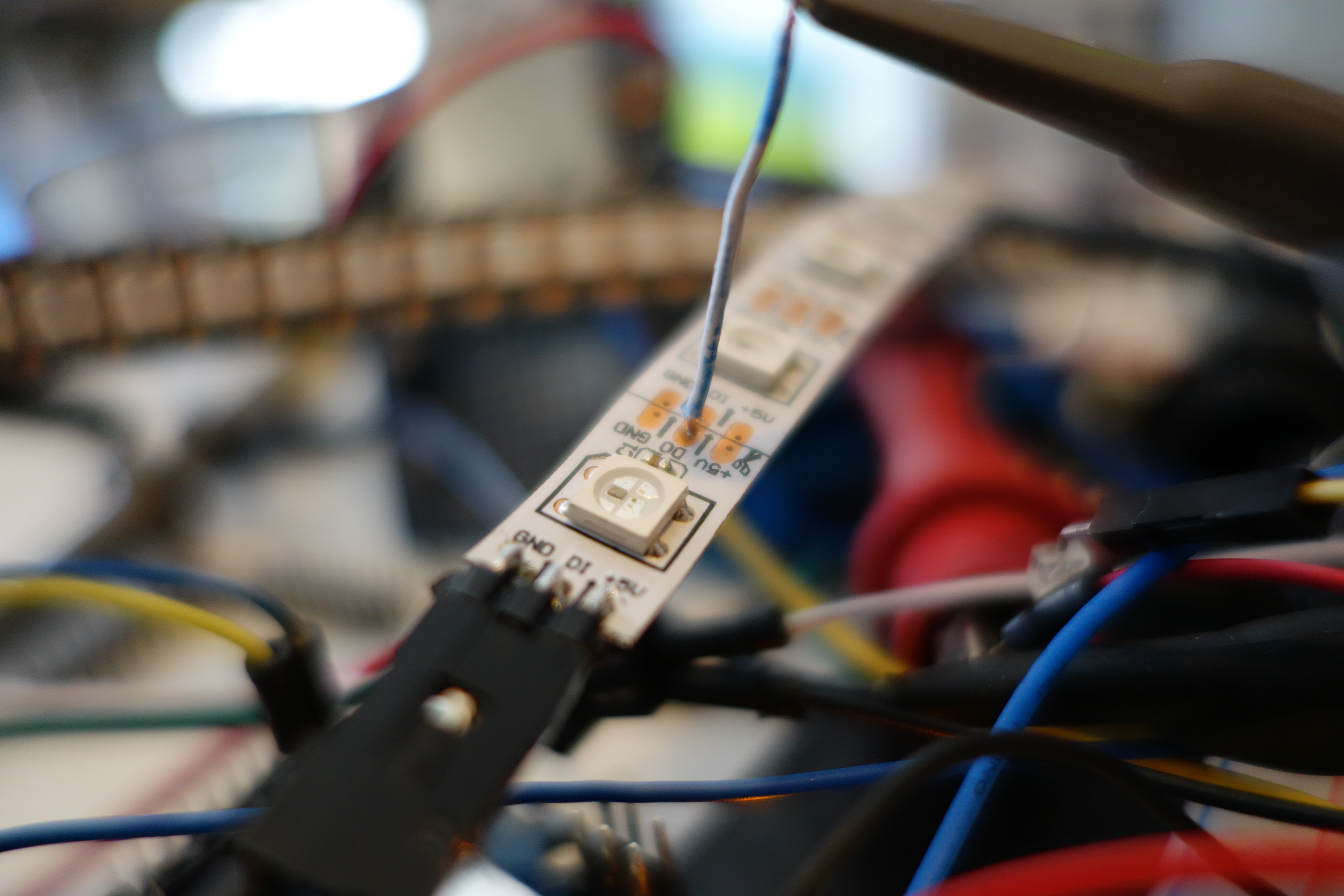
Everyone loves Raspberry Pi and everyone loves NeoPixels, so let’s get a NeoPixel directly under your Raspberry Pi’s control!

The Pi can set the NeoPixel to any RGB color and you can create scripts to update it up to 100 times per second.
For a few cents worth of parts (actually just one part!) and a single IO pin, you can give your Pi…
The possibilities are endless! Click on for a demo video and full instructions…
Using the updated Arduino 1-Wire library code presented here, you can eliminate the need for an external pull-up resistor for typical small networks of DS18B20 temperature sensors. This should also work with any AVR processor and other types of 1-Wire devices as well. You can download the updated 1-Wire library here…
https://github.com/bigjosh/OneWireNoResistor/archive/master.zip

From the DS18B20 Data Sheet
If you’ve ever used the ubiquitous (and amazingly useful!) DS18B20 family of 1-Wire temperature sensors, you’ve almost certainly used a 4.7K ohm pull-up resistor as well. Every one of the seemingly endless Arduino DS18B20 tutorials on the web starts with some version of the line “You will not be able to do anything with this senor until you go out and procure yourself a 4.7K ohm resistor”. AdaFruit is even generous enough to include one of these resistors with every DS18B20-based temperature sensor they sell (be it bare, waterproof, or hi-temp) because they know you are going to need it.
I am here to tell you that everything is about to change. If you were banking on your stockpiles of 4.7K ohm resistors to be the one reliable store of value in these uncertain times, you need to rethink your long-term asset preservation strategy because the decade-long run of stable demand for this part is about to plummet. Yes – it is now possible to connect DS18B20 sensors without any external pull-up resistor at all!
Outrageous claims demand outrageous proof, so let’s start with a brief demo that proves beyond a shadow of a doubt that this is not just a cockamamie theory, but cold hard fact…

In the PWM article, we discovered that each NeoPixel has a clock that free-runs at about 500Hrz and each pixel will only update its displayed color at the end of a clock cycle. This means that there should be about 2ms of jitter when updating a pixel, which absolutely limits the maximum refresh rate.
This sounds good in theory, but how can we actually see something that happens over the course of 1-2ms?
| UPDATE 8/7/2104:It appears that Google occasionally will randomly and silently drop the authorization for an Apps Script web app. If you notice that your spreadsheet has stopped updating and you know that your logger is still working, then you probably need to log into your spreadsheet from a web browser, go into the scripts editor, and manually execute any function in the script. This will cause a popup that will reauthorize the script and everything will then start working again.
I think this is the last straw. I can not recommend using Google for logging (or any other non-trivial application) any more. This stuff is just too flaky. Sorry. |
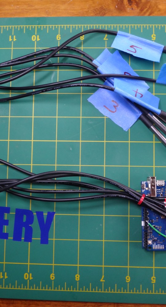
If you are like me, you often find yourself in a situation where you need to log multiple channels of temperature data. From testing nano-insulating paint to debugging an overheating geothermal well, most of us will have need of accurate and frequent temperature logs at some point in our short and brutish lives.
Here is a recipe to make a reliable, cheap, and easy cloud-based, multi-channel temperature logger using an Arduino Yun and DS18B20 temperature sensors. I chose the Yun because everyone loves Arduinos and this one can connect to the internets. I choose the DS18B20 sensors because they are awesome and cheap and accurate and you can hook up lots of them to a single pair of wires.
| UPDATE 8/6/2016:
IFTTT For Makers is also a great way to log data to a good spreadsheet. It does add an extra point of failure, but the interface is very clean and simple. |
| UPDATE 6/23/2015:
I’ve been using Wolfram DataDrop for about a month now for logging sensor data and I like it much better than Google Spreadsheets. It is reliable and well thought out, and super-duper easy to use. If you take the extra step and drink the Wolfram cool-aid (not necessary to just use the DataDrop), then you can really do some very cool things with shockingly little work. |
| UPDATE 8/7/2104:
It appears that Google occasionally will randomly and silently drop the authorization for an Apps Script web app. If you notice that your spreadsheet has stopped updating and you know that your logger is still working, then you probably need to log into your spreadsheet from a web browser, go into the scripts editor, and manually execute any function in the script. This will cause a popup that will reauthorize the script and everything will then start working again.I think this is the last straw. I can not recommend using Google for logging (or any other non-trivial application) any more. This stuff is just too flaky. Sorry. |
You want to…
Now that Google Spreadsheets can handle up to 2 million cells, they are a great place to log all your sensor data. You can easily view the live data from any computer on the internet and even publish fancy live charts and dashboards. All for free!
While superficially, it might seem like a good idea to try to pack your bits in as tightly as possible. You want to update your string as rapidly as possible to reduce transmission time. Unfortunately, this can actually cause some hairy problems that get worse as your strings get longer.
Remember how signal reshaping will take a short bit and stretch it out to make it into an “ideal” bit? If you try to be cute and pack your bits in as tightly as you can, eventually these stretched bits are going to use up the gap before the next bit and violate the VDL minimum. When this happens, you see a glitch on the string.
You might think that as long as you keep your bits at least as long as the “ideal” size, then they will not get stretched and you will avoid glitches. Unfortunately, the “ideal” bit size varies from pixel and even changes over time for a single pixel depending on temperature and voltage
Heck, you can even have cases where a chip will turn tightly packed 1-bits into 0-bits thanks to signal shaping. Take at look at this capture…

Valid 1-bit getting subverted into 0-bit by signal shaping
Here we were trying to to squeeze our 1-bits to be as small as possible while still meeting the letter of the law. The bottom blue trace shows a perfectly valid 560ns wide 1-bit (spec says 700ns ±150ns = 550ns min) coming in, but the purple trace shows it going out the other side now reshaped to a 376ns wide 0-bit. Why did it do that? Maybe it was hot. Maybe it was just having a bad day. It doesn’t really matter because if this happened to you, what you would see is that all of the LEDs past this one went black – a symptom that would surely have you wasting lots of time looking for a power or signal break. And the longer your strings, the wider the range of behavior like this you are likely to see.
Give your 1-bits and your gaps a little room the stretch their legs and it will save you all kinds of intermittent and hard to debug problems
The moral of the story: Give your 1-bits and your gaps a little room to stretch their legs and it will save you all kinds of intermittent and hard to debug problems. You don’t want to stretch your 0-bits, however, because then they might become 1-bits (see T0H maximum), instead you can stretch the gap after the 0-bit to give it some room to expand into. For some simple bit-pampering code, check out…
NeoPixels Revealed: How to (not need to) generate precisely timed signals
One of the things that makes NeoPixels so useful is that you can connect huge numbers of them end to end and they will faithfully relay your data on down the line. According to the Englishish datasheet, “Built-in signal reshaping circuit, after wave reshaping to the next driver, ensure wave-form distortion not accumulate”.
To see how this actually works, we need to go NSA on a couple of Neopixels and intercept their communications…
Going NSA on a Neopixel
I’ve placed a wiretap on the trace that connects the data-out from the near NeoPixel to the data-in of the far one.
I stuck a photo-detector on a NeoPixel to get an insider’s look at exactly how they do their PWM…

Getting physical with a NeoPixel
Looking at the photo-detector output on a scope at a 500us timescale, the PWM of the LED shows up perfectly – it is running at about 500hz (~2ms per cycle).
Here is the LED showing the lowest brightness of 0x01…

LED output at minimum brightness (0x01)
…and at half brightness of 0x80…

LED output at half brightness (0x80)
…and finally full brightness of 0xFF…

LED output at full brightness (0xFF)
We can see that the LED is never continuously on. Even when the color is set to full brightness, the LED still turns off for about 100us at the end of each PWM cycle. This means that there will always be some flicker with a Neopixel, although nothing noticeable to human eyes.
This PWM clock runs independently from the data coming in. This has some practical consequences. It means that there is up to ~2ms of jitter between when you latch new data and when it actually shows up on the LED. Here are a couple of extreme examples…

A lucky latch with very short latency
Here we see the LED come (top trace) on almost immediately after the data stops (middle trace). We just got lucky that the PWM cycle was ending just as we finished sending data.

Almost worst case of >1500ns of latency between latch and display
This time there is delay of >1.5ms (1,500,00ns!) between the end of the data and the LED lighting up. We just missed the end of the previous PWM cycle and so had to wait for the next one.
There is no practical way to avoid this jitter. Some implications include…
So now we can detail exactly a frame refresh works…
Q: Couldn’t I use a photo-detector or current probe to lock into the PWM clock and then make sure my data always ends just before the next PWM cycle starts?
A: Keep in mind that every pixel has its own independent PWM clock and they are all free-running and all have different periods due to manufacturing and environmental differences. So you probably will only be able to get your data to be optimally timed for a single pixel in the string.