Inside Neouart – Tricking a serial port into being a signal generator
Last time, we connected a NeoPixel directly to a RaspberryPi. This is certainly fun and useful, but the real motivation behind this project was to explore clever ways to make use of limited hardware resources. NeoPixels need a precisely timed string of bits to be happy. Luckily, every RaspPi comes with built-in hardware for generating strings of precisely timed bits – a serial port!
If all you care about is making pretty colors the easy way, don’t bother reading this article. If you are wondering how it is possible to reliably generate a pulse train with +/-150ns precision on a Raspberry Pi pin without kernel mods or DMA, then read on!
Why is this even hard?
The Pi is much, much faster than an Arduino so we should just be able to bit-bang our NeoPixel data out a GPIO, right?
Alas, this doesn’t work on a Pi running Linux since lots of other stuff is happening on the processor that we can’t control. We can be interrupted at any moment by another process or hardware interrupt. If that happens while we are in the middle twiddling our NeoPixel bits, then our pixel data will likely be corrupted.
We can get around this problem by off loading the signal generation to dedicated hardware with timing that is not subject to unpredictable interruptions.
neouart works by subverting one of the Raspberry Pi’s serial ports (the mini-UART) into generating a NeoPixel bitstream using the following tricks…
- constructing serial data bytes so that the shape of the generated serial output signal ends up being a valid NeoPixel bitstream
- using the UART’s break generating hardware to add a pre-amble and post-amble needed by the NeoPixel
- dynamically changing the UART’s baud rate as it is transmitting to make sure the output level is always in a known and valid state even when subject to unpredictable interruptions
- pre-stuffing the UART’s 8 byte FIFO plus the transmitter holding register to allow a complete NeoPixel transmission to occur in one continuous step without CPU involvement
Seeing the Serial Port as a Signal Generator
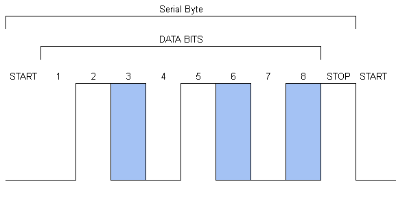
Serial ports typically convert data bytes into streams of bits surrounded with extra stuff like start and stop bits. Each of the bits is a fixed width, and that width is based on the baudrate. Here is a typical serial byte as it appears on the port’s output (this is standard 8-bit, no parity, 1 stop)…

We can control the level of each of the 8 data bits (the areas in blue) by picking what byte to send. We can not control the level of the start and stop bits, they will always be sent as low and high respectively.
NeoPixel bits are not like serial bits. They use the width of a high voltage to represent data. Here is a string of NeoPixel bits…
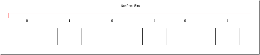
If we carefully set things up, we can manipulate the shape of the output of the serial port to look like a NeoPixel data stream. We have to work around the fixed locations of the start and stop bits, but it is possible.
Here is a template for encoding a single serial byte so that it will generate 3 NeoPixel bits when it is transmitted….
 The blue areas show where we can put out NeoPixel bit values. I’ve also shown the START bit of the subsequent serial byte because it forms the end of the final NeoPixel bit.
Here is an example showing the encoding of the NeoPixel byte 54…
 We end up with the hex serial bytes 32, 96, 12. From a data perspective, the bytes that we send to the serial port look nothing like the NeoPixel bits we are generating- they are only related by the shape of the resulting waveform. Each serial byte generates several NeoPixel bits of varying widths (but the width of every Neopixel bit is a multiple of the fixed width of a serial bit).
It takes 24 NeoPixel bits to specify the color of one pixel (8 each for red, green, and blue), so to light up a NeoPixel we need 8 serial bytes for each NeoPixel. NeoPixels also take their bits in most-significant-bit-first order, which is the opposite of normal serial port data . Here is a diagram of how to convert any 24 bit NeoPixel color into 8 serial bytes (click to zoom)…
![]()
and here is the function for actually doing the conversion…
[sourcecode language=”cpp” padlinenumbers=”true”]
// Encode a 24 bit value into 8 bytes where each byte has the format…
// 0b?0?10?10
// Where each ? is a bit from the orginal 24 bit value.
// This wonky format is designed to generate correct NeoPixel
// signals when sent out a serial port and surrounded with stop and start bits.
void encodebits( unsigned x , EncodedNeoBuffer *buffer ) {
int bits=24;
unsigned char *b = buffer->bytes;
while (bits) {
// Process 3 bits of the input into 1 byte on the output
//
// Note that we processes the input by shifting up and checking the high bit (#23)
// This is becuase NeoPixels actually take thier data in MSB first order
// while serial ports send in LSB first order
unsigned char t=0b00010010; // initialize with all the known 1’s
if (x & (1<<23) ) {
t |= 0b00000100;
}
x <<= 1 ;
bits–;
if (x & (1<<23) ) {
t |= 0b00100000;
}
x <<= 1 ;
bits–;
if (x & (1<<23) ) {
t |= 0b10000000;
}
x <<= 1 ;
bits–;
*b = t;
b++;
}
}
[/sourcecode]
We also have to make sure that the width of each serial bit is correct. We previously discovered that each NeoPixel 0 bit should be about 400ns wide and each NeoPixel 1 bit should be able 800ns wide. Since we are making a NeoPixel 0 bit out of a single serial bit and a NeoPixel 1 bit out of 2 adjacent serial bits, we want each serial bit to be about 400ns.
Here is the formula from the data sheet for computing the mini_UART baudrate divisor…
![]()
Knowing that the Raspberry Pi system clock runs at 250mhz, we can compute the baudrate_reg using this code…
[code lang=”cpp”]
// Timing constants
#define CPU_FRQ (250000000) // Main system clock at 250mhz
#define BIT_FRQ (1000000000/400) // Target output bit width = 400ns as per WS2812data sheet. Note that we will make the H and L data pulses out of 1 or 2 of these bits
#define UART_FRQ (BIT_FRQ*8) // There are uart 8 cycles per bit on the mini uart BAP11
#define BAUD_DIV (CPU_FRQ/UART_FRQ) // How many cpu cycles per UART cycle?
// Note that this calculation rounds down to a divisor of 12, which yields a bit width of 480ns which is perfect for NeoPixels!
AP( aux, AUX_MU_BAUD_REG) = BAUD_DIV-1; // direct access to the 16 bit baud rate counter, the register gets the divisor – 1 as per BAP19
// Set the real target baud rate, which will speed up the remaining bits in the transmitter
[/code]
Beginnings and Endings
Now we can successfully generate the actual NeoPixel data bit stream, we still have to deal with what happens before and after those data bits. The idle state for a NeoPixel data line is a low voltage, while the idle state for a serial line is a high voltage.
We can get around this by using the serial port’s break generator. A break is a special condition used in some serial connections and consists of a long time period of low voltage. On the Pi’s mini_UART, we can generate a break by writing a 1 to the AUX_MU_LCR_REG_BREAK bit. The output of the serial port is the logical AND of the data and the break generator, so the serial port will be forced to a low when break is enabled even if data bits are being transmitted. It takes some fancy footwork to make sure that we generate our break at exactly the right times and neither let the serial idle show up on the output, nor let our break cover any transmitted data bits.
Here are the steps to begin transmitting…
- Always start from an idle state. No data is being transmitted and break is asserted, so line is low.
- Disable the transmitter so no bytes will actually be transmitted yet.
- Load the FIFO up with all 8 serial bytes so they will be ready to go as soon as we open the gates.
- Set the baudrate of the serial port to the lowest possible value to stretch out the first bit transmitted and give us as much time as much as possible in case we get interrupted anywhere during steps 4-7.
- Enable the transmitter and wait for the first bit to show up on the output. Note that the first bit is always a start bit which is low.
- Turn off the break generator. Now the output will be showing the first transmitted bit rather than the break signal. Since the bit being transmitted is also a low, the actual output doesn’t change.
- Set the baudrate to the computed value to generate valid NeoPixel bits. As soon as we do this, the rest of the data in the FIFO starts quickly streaming out of the serial port and autonomously generates the complete NeoPixel data stream.
Here is a timeline of the beginning of a transmission…
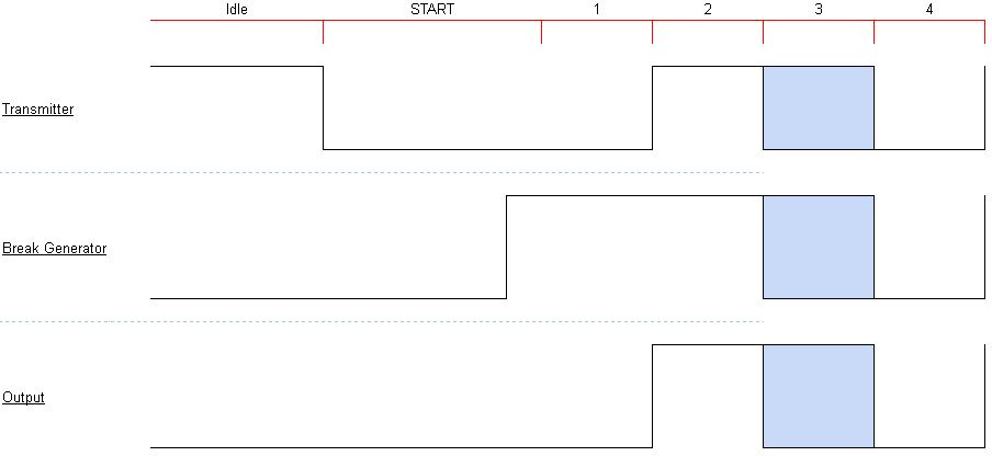
Note that the START bit is wider than the other bits because this bit is being transmitted at a very low baudrate until after the break is disabled. All of this extra complexity is to make sure that the output stays in a valid state no matter where we might be interrupted.
Things are easier at the end of a transmission because the NeoPixel will already have gotten all the data it needs so timing is not as important. We stick a trailing zero byte into the FIFO just to make sure the final NeoPixel bit is terminated correctly. Once the transmission is compete, we turn break on again to cause the pixel to latch and also to leave the output low until the next transmission.
You can find the heavily commented code for neouart on GitHub.
FAQ
Q: Why did you use the mini-UART rather than the real one?
A: The mini-UART is handy for 2 reasons…
The mini-UART it is driven from the main CPU clock that is running at 250Mhz
By contrast, the real PL011 UART is clocked off a special clock that is set too slow for NeoPixels by default, so it would require a change to /boot/config.txt and a reboot to get working right.
The mini-UART is not normally used on the Pi
By contrast, the real PL011 UART is typically hardwired as a Linux boot console and so we’d need to make changes to dmseg and kill the control process to be able to get exclusive access ourselves.
That said, the changes to use the PL011 UART are not hard and I do have code that works on it. The primary benefit is that the PL011 UART has a 16 byte FIFO whereas the mini-UART only has 8 bytes. This means that we could drive two NeoPIxels worth of data rather than just one. Unfortunately, driving two NeoPixels needs twice as much power. This might be more than you can grab just from the Pi’s 3V3 pin.
For purposes of this article, I wanted to make things as easy as possible so pretty much anyone could get it working in a couple of minutes, and even just one NeoPixel is super useful and fun!
Q: Can’t I just add a little code to keep writing more data to the serial port and then drive a whole string of NeoPixels rather than just one?
A: Not reliably. Our program is under Linux and we could get interrupted at any moment. When we are put on pause, we can’t send any more data and so the FIFO quickly drains and runs out of data and has nothing left to send. When this happens, the transmitter goes idle and starts sending a steady high voltage. If we are paused for more than about 10us (not very long), then the NeoPixel resets. When we finally wake up again and resume sending the remaining bits, they will all be in the wrong places. Even if we are paused for less than 10us, if the bit we were sending was a 0-bit, then it will likely get stretched to a 1-bit and corrupt the received color.
Q: Why not just use an interrupt triggered driver to keep the FIFO filled?
A: This works great, but I could not figure out any way to hook the interrupt without using a kernel mod. Unfortunately, it is hard to write instructions to let beginners easily and reliably install a kernel mod. There are lots of different Linuxes that people run on their Pi’s, and lots of people playing with Pi’s are beginners (yeay beginners!). Trying to walk a beginner though the steps of compiling and installing a kernel mod is just going to make them sad. That said, I really don’t know anything about Linux so if there is a good way to distribute a Linux driver that can be installed by beginners and almost always work (or at least fail in predictable ways), please let me know!
Q: How about ditching Linux and going bare-metal Pi?
A: This works great and is easy, but kind of ruins the point of using the Pi in the first place. If you don’t care about Linux, get an Arduino! :)
Q: How about usermode DMA?
A: Stay tuned!
Q: How did you make the diagrams?
A: A Google Spreadsheet!
Again, some very clever stuff. Cool. Unfortunately, I can’t achieve >2 MBits/s on a 8 MHz AVR for the <500ns bit times.
Here is a cool command line tool that can make streams of serial chars to drive a NeoPixel…
https://blog.pwkf.org/2024/03/20/drive-ws2812-uart.html