Battery Fuel Gauge with Zero Parts and Zero Pins on AVR

It can be nice to know how much battery power you have. It becomes critically important with LiPo batteries since you can permanently damage them by running the voltage down too low. Typically battery voltage detection requires adding a circuit with extra parts and their associated power requirements. Wouldn’t it be great to be able to do this using nothing but software? Read on for a no parts, no pins, no power solution…
Perfunctory Video
Normal Low Battery Detector Circuit
Here is a typical by-the-book low battery detector for LiPo-powered devices…

The voltage divider R5/R9 scales down the battery voltage, where it is compared to an integrated reference voltage inside U3, which outputs a LOWBAT signal that would typically connect to an input pin on your micro-controller.
This circuit works fine and will indicate when the battery voltage drops below the threshold voltage (about 3.6 volts with the above values), but it has a few drawbacks…
- The voltage divider formed by R5 and R9 is always drawing current – 12uA at the low cutout voltage.
- The comparitor U3 is always drawing current – typically ~2.5uA at the cutout voltage.
- The pull-up resistor R6 is drawing ~7.6uA whenever there is a low battery.
- Requires a dedicated input pin on your micro-controller.
- Requires 5 physical parts that cost money and use up board space.
- Can only detect a single hardwired threshold voltage.
- The threshold voltage depends on the tolerances of R5 and R9, and there is no way to calibrate it.
Do we really need 5 parts, an input pin, and >20uA of constant power draw just to detect a low battery?
Do we really need 5 parts, an input pin, and 20uA of constant power draw just to detect a dead battery?
Power is precious, especially if you are using an adorably small LiPo battery. And this circuit continues to pull power even after it has detected a low battery condition- there is no way to turn it off. We can do better…
The Zero Part, Zero Pin, Zero Quiescent Power Solution
Thanks to the AVR’s flexible analog-to-digital converter, you can accurately detect battery voltage completely in software, without sacrificing a single pin or adding a single part to your design! And it does not draw any power when not in use! Yeay!
From the datasheet…
The ADC converts an analog input voltage to a 10-bit digital value through successive approximation. The minimum value represents GND and the maximum value represents the reference voltage.The voltage reference for the ADC may be selected by writing to the REFS1:0 bits in ADMUX. The VCC supply, the AREF pin or an internal 1.1V voltage reference may be selected as the ADC voltage reference.
Typically you would be measuring an unknown voltage (like an input pin) against a known scale (a reference voltage). Our trick is that we are going to do the opposite – we are going to measure a known voltage (the internal 1.1 volt reference) using an unknown scale (the Vcc voltage). Normally it would be silly to measure a known voltage (we already know what it is!), but in this case it will let us reverse-calculate the reference voltage. I wonder if this is what the engineers who designed this chip had in mind when they made it possible to use the internal reference as a input?
Normally it would be silly to measure a known voltage (we already know what it is!), but in this case it will let us reverse-calculate the reference voltage.
Here is a diagram of the analog-to-digital block with the two sources we will be using highlighted…
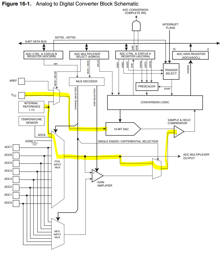
How do we actually compute the Vcc voltage? Back in the data sheet we find…

ADC here is the result value output by the analog to digital converter.
In our case, Vin is the internal 1.1 volt reference voltage and Vref is the Vcc power supply voltage. If we substitute those in, we get…
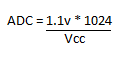
…and (if you were awake the 3rd week of 7th grade) algebra gives us…
Vcc = (1.1v * 1024) / ADC
It is so simple a child could do it! We can now compute the current Vcc voltage based solely on the output of the analog to digital converter! But what are we actually doing here?
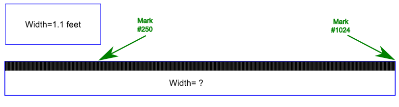
Imagine that I gave you a stick that had 1024 evenly spaced markings along the length of it. I also gave you another shorter stick and told you that it was exactly 1.1 feet long. Could you figure out how long the longer stick was?
Of course you could! All those LSAT prep classes weren’t a waste after all!
You would take the short stick and measure it with the longer stick and count how many marks long it was. Let’s say it was 250 marks long. So…
250 marks = 1.1 inches
1 mark = 1.1 inches/ 250
1 mark = 0.0044 feet
If 1 mark is 0.0044 feet, and we know the long stick is 1024 marks long, then we know that the long stick is 1024 marks * 0.0044 feet per mark = 4.5056 feet. Our long stick is ~4.5 feet long!
Now change [feet] to [volts] and [marks] to [steps of the analog to digital converter] and… we measured the 1.1 internal reference voltage using a scale that is based on our unknown Vcc voltage and we got an ADC value of 250. This means that our Vcc is at ~4.5 volts!
How precise is this technique? The higher the Vcc, the lower our resolution so let’s take the worst case which is at the device’s maximum allowed Vcc of 5.5 volts. At this limit, a step of the ADC is equal to ~5mV. That is a couple of orders of magnitude more resolution than we need for competent state-of-charge battery measurements, which typically only call for 10ths of volts of resolution.
How accurate is this technique? The two main sources of inaccuracy are (1) the fact that the internal reference can range from 1.0 volts to 1.2 volts depending on manufacturing processes, and (2) the inherent inaccuracies of the ADC. Practically speaking I’ve found these Vcc measurements to be accurate to within 0.1 volts right out of the box. If you were going to use these measurements for, say, detecting the cut-off charging voltage for a LiPo battery, then you could calibrate the exact ADC measurement that matched the target voltage for each individual device and probably get within 10’s of millivolts.
Enough chat chat! Show me the code!
This file contains hidden or bidirectional Unicode text that may be interpreted or compiled differently than what appears below. To review, open the file in an editor that reveals hidden Unicode characters.
Learn more about bidirectional Unicode characters
| /* | |
| * NoPartsBatteryGuageAVR.c | |
| * | |
| * This is a simplified demonstration of how to detect power supply voltage by using the on chip | |
| * analog-to-digital converter to measure the voltage of the internal band-gap reference voltage. | |
| * | |
| * The code will read the current power supply voltage, and then blink an LED attached to pin 6 (PA7). | |
| * | |
| * 1 blink = 1 volts <= Vcc < 2 volts (only applicable on low voltage parts like ATTINY84AV) | |
| * 2 blinks = 2 volts <= Vcc < 3 volts | |
| * 2 blinks = 2 volts <= Vcc < 3 volts | |
| * 3 blinks = 3 volts <= Vcc < 4 volts | |
| * 4 blinks = 4 volts <= Vcc < 5 volts | |
| * 5 blinks = 5 volts <= Vcc | |
| * | |
| * 0 blinks = power supply turned off :) | |
| * | |
| * This code was tested on an ATTINY84A with default fuse settings, but should work unchanged on | |
| * any ATTINYx4 or ATTINYx4A, and should be easily ported to any 8-bit AVR with ADC and internal 1.1 reference voltage. | |
| * | |
| * More info at… | |
| * | |
| * http://wp.josh.com/2014/11/06/battery-fuel-guage-with-zero-parts-and-zero-pins-on-avr/ | |
| * | |
| */ | |
| //Comments in slash/asterisk form are quoted from the datasheet | |
| /* | |
| The device is shipped with CKSEL = “0010”, SUT = “10”, and CKDIV8 programmed. The default | |
| clock source setting is therefore the Internal Oscillator running at 8.0 MHz with longest start-up | |
| time and an initial system clock prescaling of 8, resulting in 1.0 MHz system clock. | |
| */ | |
| #define F_CPU 1000000 | |
| #include <avr/io.h> | |
| #include <util/delay.h> | |
| // Returns the current Vcc voltage as a fixed point number with 1 implied decimal places, i.e. | |
| // 50 = 5 volts, 25 = 2.5 volts, 19 = 1.9 volts | |
| // | |
| // On each reading we: enable the ADC, take the measurement, and then disable the ADC for power savings. | |
| // This takes >1ms becuase the internal reference voltage must stabilize each time the ADC is enabled. | |
| // For faster readings, you could initialize once, and then take multiple fast readings, just make sure to | |
| // disable the ADC before going to sleep so you don't waste power. | |
| uint8_t readVccVoltage(void) { | |
| // Select ADC inputs | |
| // bit 76543210 | |
| // REFS = 00 = Vcc used as Vref | |
| // MUX = 100001 = Single ended, 1.1V (Internal Ref) as Vin | |
| ADMUX = 0b00100001; | |
| /* | |
| By default, the successive approximation circuitry requires an input clock frequency between 50 | |
| kHz and 200 kHz to get maximum resolution. | |
| */ | |
| // Enable ADC, set prescaller to /8 which will give a ADC clock of 1mHz/8 = 125kHz | |
| ADCSRA = _BV(ADEN) | _BV(ADPS1) | _BV(ADPS0); | |
| /* | |
| After switching to internal voltage reference the ADC requires a settling time of 1ms before | |
| measurements are stable. Conversions starting before this may not be reliable. The ADC must | |
| be enabled during the settling time. | |
| */ | |
| _delay_ms(1); | |
| /* | |
| The first conversion after switching voltage source may be inaccurate, and the user is advised to discard this result. | |
| */ | |
| ADCSRA |= _BV(ADSC); // Start a conversion | |
| while( ADCSRA & _BV( ADSC) ) ; // Wait for 1st conversion to be ready… | |
| //..and ignore the result | |
| /* | |
| After the conversion is complete (ADIF is high), the conversion result can be found in the ADC | |
| Result Registers (ADCL, ADCH). | |
| When an ADC conversion is complete, the result is found in these two registers. | |
| When ADCL is read, the ADC Data Register is not updated until ADCH is read. | |
| */ | |
| // Note we could have used ADLAR left adjust mode and then only needed to read a single byte here | |
| uint8_t low = ADCL; | |
| uint8_t high = ADCH; | |
| uint16_t adc = (high << 8) | low; // 0<= result <=1023 | |
| // Compute a fixed point with 1 decimal place (i.e. 5v= 50) | |
| // | |
| // Vcc = (1.1v * 1024) / ADC | |
| // Vcc10 = ((1.1v * 1024) / ADC ) * 10 ->convert to 1 decimal fixed point | |
| // Vcc10 = ((11 * 1024) / ADC ) ->simplify to all 16-bit integer math | |
| uint8_t vccx10 = (uint8_t) ( (11 * 1024) / adc); | |
| /* | |
| Note that the ADC will not automatically be turned off when entering other sleep modes than Idle | |
| mode and ADC Noise Reduction mode. The user is advised to write zero to ADEN before entering such | |
| sleep modes to avoid excessive power consumption. | |
| */ | |
| ADCSRA &= ~_BV( ADEN ); // Disable ADC to save power | |
| return( vccx10 ); | |
| } | |
| int main(void) | |
| { | |
| // Enable output for LED pin | |
| DDRA |= _BV(PORTA7); | |
| while(1) | |
| { | |
| // Read the current Vcc voltage as a 2 decimal fixed point value | |
| uint8_t vccx10 = readVccVoltage(); | |
| // Convert to whole integer value (rounds down) | |
| uint8_t vcc = vccx10 / 10; | |
| // Indicate the Vcc voltage by blinking the LED Vcc times… | |
| for(int i=0;i<vcc;i++) { | |
| PORTA |= _BV(PORTA7); // Turn on LED | |
| _delay_ms(250); | |
| PORTA &= ~_BV(PORTA7); // LED off | |
| _delay_ms(250); | |
| } | |
| _delay_ms(1000); // Pause before next round | |
| } | |
| } |
Circuit Drawings


FAQ
Q: Since the bandgap voltage reference is 1.1 volts, doesn’t this limit the minimum supply voltage I can measure to 1.1 volts?
A: Theoretically yes, but since a typical AVR cuts out at either 2.7 volts (or 1.8 volts for V series parts), this is not a practical limitation since the chip would already be non-functional.
Q: Won’t the battery automatically disconnect before the voltage gets low enough to damage it?
A: Some LiPo batteries come with a protection board attached and this board will typically disconnect when the voltage drops dangerously low, but not all batteries have this board – and you still probably don’t want to let your batteries get low enough to trigger the board since the number of cycles a battery can survive is dependent on the depth of discharge.
Q: Doesn’t the datasheet say that “Internal voltage reference options may not be used if an external voltage is being applied to the AREF pin”, which would imply that you would loose the use of the AREF pin (pin 13) for other functions?
A: The datasheet also says that when “Vcc [is] used as analog reference, [the ADC is] disconnected from PA0 (AREF)”, which make sense. Hmmm… I’ve actually tested this and applying an external voltage to pin 13 does not seem to affect the ability to use the internal reference at all. I have an open case with Atmel to get a clarification on this and will report back.
UPDATE 11/11/2014- I got a clarification from Atmel that on the ATTINYx4A the AREF pin is, in fact, disconnected when the Vcc is used for the Vref. My guess is that the conflicting sentence was mis-copy/pasted from another part like the ATMEGA48A which does apparently have this limitation…
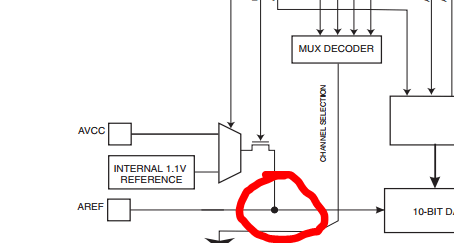
From Figure 24.1, ATmega48A/PA/88A/PA/168A/PA/328/P [DATASHEET]
A: True, the ADC does draw a tiny bit of power (100’s of uA) while it is actually doing a conversion, each conversion only takes a tiny bit of time and the rest of the time you can disable the ADC. Most importantly, the ADC is not drawing any additional current when the chip is sleeping and in shut down because of a low battery.
Q: I’m trying to do low battery detection on an ATTINY25/45/85, but I can’t figure out how to set Vin to the internal reference?
A: Apparently the ATTINYx5 does not have a Vin connection for the internal reference, so we have to get a bit more tricky. The basic idea is to do two samples – first sample the internal temp sensor using the internal 1.1v as Vref, and then sample the temp sensor again, but using the Vcc as the Vref. Since the voltage of the temp sensor is very low, you will not get great resolution but it should still be good enough for battery level gauging, and you can again do some calibration if you need more accuracy.
Now my question is Can this be ported to an atmega328p easily and could you give me an idea of what port names here should be changed and what should they be changed to? I would like to play with your code on my friendly 328p but with my limited knowledge it will take me a week to research which ports should be which.
Looking quickly at the datasheet, looks like want ADMUX= 0b01001110 (use Vcc as reference, bandgap as Vin). Alternately, you could connect the Vcc pin and the AREF pin together and use ADMUX=0b00001110 (use AREF as reference, bandgap as Vin).
You’d also probably need to change you prescaller since you are likely running your 328 faster than the 1mhz my lowly ATTINY is running at. In this case you can try ADCSRA |= 0b00000111 to uses the highest possible prescaler.
Everything else should be the same, I think. LMK if it does work and we will figure it out!
Ta, will see if I can get it running
This is the first non compiling line
DDRA |= _BV(PORTA7);
Tried PORTA5 and A0 to no avail
Message from compiler is DDRA was not declared in this scope so that means it could not find a class for DDRA right?
PORTA7 is just where I happened to connect the LED I was blinking in the example.
If you want to blink an LED, then use what ever PORT/PIN you connect your LED to for the DDRx and PORTx statements.
-josh
There is no PORTA in ATMega328P. Try to use another port ;-)
Changed PORTA to PORTB everywhere and it compiles Thanks
This trick is also applicable to various PICs that have the fixed voltage reference available to the ADC as a measurement input. Potential tip on some parts: Route the FVR to the DAC (DAC output pin need not be enabled), and then measure the DAC – seemed to improve accuracy in my tests vs measuring the FVR directly, but YMMV.
Yes, many PICs and even the MSP430 have similar handy functionality baked in.
Nice, couple of suggestions:
1. Why not have it do two sequence blink to get the millivolt reading as well.
2. You can use the sleep mode and provide a longer delay between readings, saving some time. Or you could add a button to wake up and take a reading.
3. By measuring the actual resistance of your voltage divider network, you could program an adjustment to the voltage formula to get better accuracy. -Fouth Grade math!
This works on the t85 without any temperature sensor reading tricks. The mux setting for Vbg is MUX[3:0} 1100 – see table 17-4 in the datasheet.
Set REFS1 & REFS0 to 0 for Vcc.
New ATMEL app note describes this approach…
Click to access 00002447A.pdf
Hi, i tried out this example on the attiny85 and got it to work after changing line 57
from: ADMUX = 0b00100001; to: ADMUX = 0b00001100;
explaination:
bitnum: 76543210
ADMUX: 00001100
bit 6 is the ADLAR bit on the attiny85 that sets the left adjustment for the adc, we do not want the result left adjusted if we read the adc like it is done in the code (see line 96-101)
bit 3-0 set the MUX to the internal 1.1v reference as @Nerd Ralph pointed out.
A library to do this…
https://github.com/cygig/MCUVoltage