The mystery of the Zombie RAM
It all started one bright morning when I wondered: Can the RAM memory on an AVR chip continue to store data after power is removed? If it can hold the data even just for a brief moment, then that could be very useful in a project I am working on.
To test it, I wrote a tiny little program that would check for a a special value in RAM (a “magic cookie”) upon power up and light an LED if it saw the right value…
#include <avr/io.h>

#define MAGIC_COOKIE 0xee00ff55UL // Nice cookie to exercise bits

unsigned long ram_cookie;

void init0 (void) __attribute__ ((naked)) __attribute__ ((section (".init0")));

// This code will be run immedeately on reset, before any initilization or main()

void init0(void) {

    DDRD = _BV(0); // Enable output on LED on pin 19

    if (ram_cookie==MAGIC_COOKIE) { // Is the cookie there?

        PORTD = _BV(0); // Light the LED!

    }

    ram_cookie = MAGIC_COOKIE; // Load the cookie for next run

    while (1); // All done

}

// We never make it to main()

int main(void)
{
}
I also built a very simple circuit with an ATTINY4313 so I could try turning the power off for various amounts of time to get a feel for how long the memory would last without power…
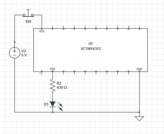
The idea is that you press the button for a little while to remove power from the chip. If the LED goes on when you let go, then the “cookie” was still valid in RAM and so was safely retained while the power was removed. I was careful to try and make sure that there was no place that power could leak into the circuit when the button was pressed.
After only about 10 minutes of work I was ready to start testing!
Initial results were extraordinary. It seemed like the little AVR could reliably hold data without power for a very long time. I tested progressively longer and longer times, getting up to 10 minutes without power and each time it came back to life with the cookie still intact. My finger got too tired to test any longer.
I was very excited. If you could reliability store data in RAM for more than 10 minutes without power, then this could be a great alternative to FLASH and EEPROM memory in many applications. 10 minutes is long enough to safely change a set of batteries. Don’t get me wrong – EEPROM and FLASH are great and can hold data for decades without power, but they are also thousands of times slower than RAM and they wear out if you use them too much.
So I went ahead and updated my project to use RAM and connected it all up and… it just didn’t work at all. The RAM did not reliably survive the power loss. I was confused. I had to figure why it had worked so well in testing but not at all in the real application. What was different in the project? I slowly cut away parts of the full project until I was left with nothing more that original test setup – and it still did not work. Did I use the same physical chip that I had used the first time? Was there some way I was accidentally powering that first test? Had I accidentally left the debugger connected on the test circuit?
When faced with a really frustrating situation like this sometimes the best thing to do is goto sleep, so I did.
The next morning my mind was fresh and I was sure I would be able to track down the problem. I fired everything up and… now it worked! Ahhhh!!! What was going on? I was sure it was not working the night before and I had not touched anything between then and now. Argh.
So I went ahead and built another full circuit and, of course, again it did not work at all- just like the last full circuit. Luckily this time I had kept the test circuit built just in case. I fired it up and…. it didn’t work either! Ahhhhh! Now I had two not-working circuits and I was getting really, really confused.
Knowing now that I had not changed anything about the test circuit between it working and not working, I assumed the change must be something in the environment. Higher temperatures could plausibly affect RAM data loss since it could lead to higher thermal noise in the silicon. Humidity also seemed like a reasonable candidate since that could possibly allow more leakage current through the air.
I frantically built an Ardunio-controlled rig that could automatically run continuous test passes on the circuit . It varied the power-off time for each pass while logging the results along with the ambient temperature and humidity. I used relays to completely “air gap” isolate every connection to the chip under test while power was off to be 100% sure that I was not leaking current into it anywhere.
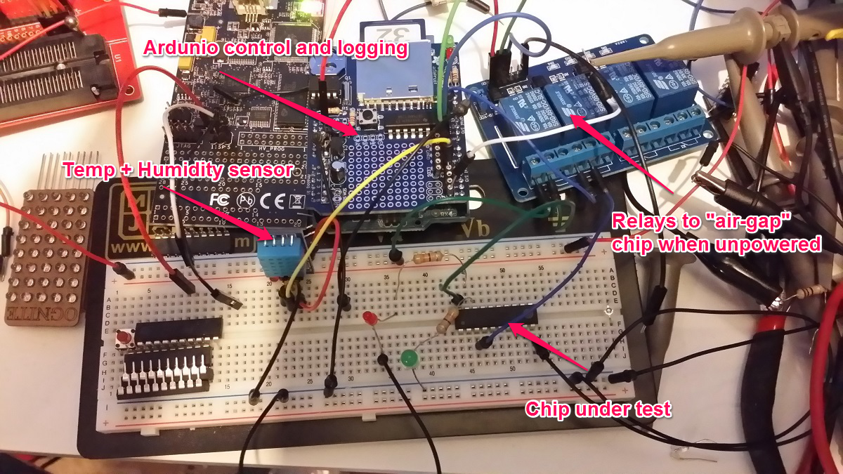
Automated Zombie RAM testing & logging rig
I let that thing run for the rest of the day through thousands and thousand of test passes, but not once did the test circuit ever retain the data longer than 100ms without power – nothing like the 10+ minutes of persistence I was seeing before. I finally had to turn off the testing rig because the rapidly clicking and clacking relays were incompatible with sleep.
The next morning I got up and turned the test rig on again and immediately noticed that the delay between relay clicks was growing longer and longer – indicating successful passes. It quickly made it back up to 10 minutes of retention without a single lost byte. I let it run for a few hours more until the clicks started getting shorter indicating RAM errors. I had all the data from both runs logged, so now it was just a matter of figuring out what was different!
After a bit of number crunching it became clear that neither temp nor humidity were correlated at all with the data retention times. Not even a bit.
It took a good long hour before I finally figured out what was causing these spooky effects and now I can readily control the data retention time of my test circuit – without even touching it.
Can you figure out what mechanism was at work here?
awesome research !! imagine for how long a capacitor could keep attiny RAM alive…
great work !!
I found that if you short the Vcc pin to ground while the chip is unpowered, then you loose the memory contents immediately. There probably is a tiny capacitor at work here – the intrinsic capacitance of the circuits on the chip itself. Now if you were going to splurge and use an actual external capacitor then you’d have so much excess power that you mind as well leave the chip powered in deep “shutdown” sleep. You should be able to get at least a 7 hour ride out of a 1000mF capacitor assuming you start at 5V and run down to 1.8V at a typical current draw of .15ua.
Very cool, can’t wait to find out how much current is needed to keep the RAM alive! I’d be careful about powering the chip through a pin other than Vcc tho…
This Atmel app note indicates that the clamp diodes can handle a sustained 1mA and more for a short period of time. This LED is making several orders of magnitude less than that, so should be ok!
Reblogged this on Electronic Technician.
Very interesting article, thanks. I had a look at your code and saw this line:
void init0 (void) __attribute__ ((naked)) __attribute__ ((section (“.init0”)));
From what I determine, this makes the code start with that function instead of main. Could you explain a bit more why you are doing this and how the code works. Or where I can get more information on this. Also is there a reason you did not want to run the code in main()?
The “naked” tells the compiler to omit the entrance and exit code for the function – so this compiled function will not get a return at the end. The init0 tells the linker to put this in section init0 which is where the very first code gets run right after the processors boots up. This is important because the normal C startup code clears all variables to their initial values (or zero), so we wouldn’t be able to see what was left in there. For more info on startup stuff and avoiding it, check out my post here..
“And I would have gotten away with it too, if it weren’t for you meddling kids.”
the SUN…!
but still, it keeps the data in RAM for 150ms right..?
It seems to be reliable up to about 100ms in my test rig, but this is very dependent on the circuit layout. You really have to test the exact circuit you plan on using in situ to be sure.
Brilliant, it was like reading a mystery book about circuits!
Fascinating. My first thought was that the effect was due to static inductance or discharge, though that didn’t explain the fact that it the RAM remained unchanged in the morning.
The code is oddly cut off in this post and in others of yours. I don’t think it’s my computer, I checked it on both Firefox and Chrome, though browser standardization is enough that a simple code td shouldn’t appear radically different from one to the other, and I’ve noticed it happening on your other posts as well. I love your code, it’s amazing, but it’s a bit hard to read because it’s cut off. (Pic enclosed, http://i.imgur.com/AlMDpjC.png).
AT least for this post, that’s all the code there is. All it does on power up is check the cookie, then light the LED if the cookie is right, then set the cookie, then go into an infinite loop. That’s it!
I have just come across your very interesting experiment. I should have realised what was happening as recently I had two PIC projects running both self powered with a common ground and many interconnected port pins. I wanted to reset one PIC and as the reset pin was used as an input I decided to toggle the power to reset. However it didn’t work and after a bit of experimenting I realised one PIC was being powered by the port pins of the other PIC project! With your experiment I did wonder with your test circuit configuration, if the LED anode was connected to the VCC rail and pulled low by the port pin whether it would work better or not at all as it would now power the AVR through the Vcc pin?
Andrew
Australia.
Good question! My guess is that would probably continue to power the chip if the output pin was HIGH or HI-Z because as soon as the chip voltage started to go down, the high side clamping diode would shunt the voltage from the pin to the chip’s power rail (the drop across the diode at those low current levels would be negligible). But what would happen if the pin was LOW? My guess is that the chip would brown out, and if it reset with the pin HI-Z then it would cycle up and down like that. But you’ll have to test and let us know what you find!
Awesome sauce
Very interesting issue!
I have a similar issue. I was trying to keep down my mini pro power comsuption with two spi sensors attached (bme280). With all properly wired, i couldn’t go below 3mA in my use case, which is deep sleep 8sec, for 8 times and then read from the two sensors ( so i have temperatura and humidity each minute aprox). When sleeping, sensors were still running and using power…so I decided to put all spi pins (miso,cs,…etc) as inputs between wakeups. And voilá…current went down to 90uA…But, then i realized that i had forgotten to connect Vcc to the sensors…so they were in fact running with power extracted from the other pins…And still are running this way…