

Last time, we made one-shot pulses using the AVR’s built in hardware timer module. Today we are going to dive deep into the datasheets to see how this technique is able to coax the normally free-running timer into generating a single pulse. Along the way, we will learn about the low level rules that govern the operation of the timer, and use a trick or two to get around those rules. Read on!…
A Simple Timer
The AVR Timer hardware has lots of modes. For this technique we will be using Fast PWM mode 7…

…which follows these fundamental waveform generation rules (excerpted from the data sheet)…
- The counter counts from BOTTOM to TOP then restarts from BOTTOM.
- The output is set when the counter equals MATCH.
- The output is cleared at BOTTOM.
That’s it. Seems straight forward, but with such simple rules how are we going to be able to find a loophole to drive our pulse train though?
The Way Things Are Meant To Be
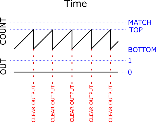
In normal operation, these simple rules generate a nice repeating waveform like this…

Moving the MATCH closer to TOP gives us less “on” time in our repeating square wave, while moving MATCH closer to BOTTOM give us more “on” time.
The Out Of Bounds Match
What happens if we mix things up and set MATCH to be higher than TOP? It sounds like crazy talk, but these are all just numbers inside a chip and we can set the numbers to whatever the hell we want. The chip will continue to follow its rules no matter what numbers we shove in there.
With MATCH higher than TOP, the counter will follow its rule and reset back to BOTTOM every time it hits TOP, but it will never hit MATCH. It will also still follow its rule and clear the output each time it resets back to bottom, but the output is already clear so it just stays clear. Because it never makes it up to MATCH, the output will never get set. The output will stay low forever…
Upsetting The Pattern
Well, that is not very useful. But while this futile Timer-to-nowhere is impotently counting away, what if we throw a monkey wrench in and directly set the counter to a value that is higher than TOP but lower than MATCH? The counter will continue following the rules and dutifully keep counting up from where ever we set it. It will eventually hit MATCH, and when it does it will set the output just like it is supposed to according to the rules…
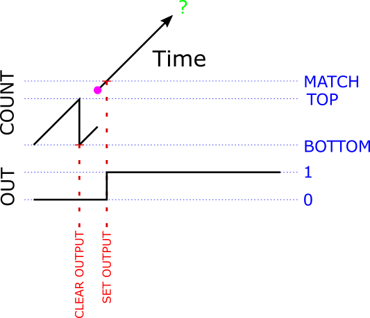
(The purple dot shows the moment we manually set the counter to a value between TOP and MATCH)
We are half way there! We have figured out how to at least make the beginning of a pulse, now we just have to come up with a good way to end it.
Counter To Nowhere?
It looks like the counter is just going to keep counting up and up forever and never hit MATCH or TOP or anything else except infinity. Luckily, the counter is just a register and registers are just composed of a bunch of bits – 8 bits in this case. The largest binary number you can hold in 8 bits is 11111111 (that’s 255 in decimal). The data sheet calls this number MAX, and if you increment MAX by 1, you end up at 00000000 (that’s zero). It is called overflow or rollover. Normally overflowing a register is bad, but in this case it is very nice. It takes us shoots-and-ladders-style right back down to BOTTOM, which is a good place for us to be. Remember that according to the rules, the output is cleared whenever we hit BOTTOM, so we get this…
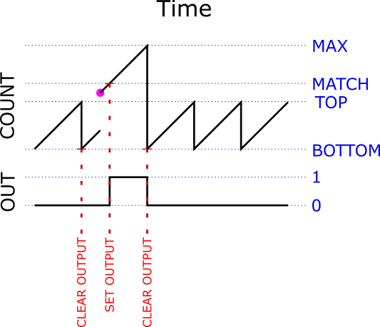
(Again, the purple dot shows the moment we manually set the counter to a value between TOP and MATCH)
Look at that! We have a one shot pulse! Sweet!
Total Control
If you look carefully at moment where we hit MATCH and set the output, you’ll notice that by moving MATCH closer MAX, we also make the width of the pulse shorter…
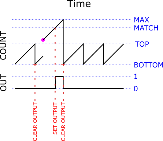
Moving MATCH away from MAX similarly makes our pulse wider. So we can precisely control the width of our pulse by carefully picking the value we give MATCH.
The Big Picture
Our pulse generation strategy just boils down to…
- Set TOP lower than MATCH. Now the Timer is free-running, but constantly outputting a 0.
- Set MATCH to any value we want. Picking a MATCH that is close to MAX makes a shorter pulse, farther away makes a longer one. As long as we set MATCH higher than TOP, then the counter will never reach it on its own so we can modify MATCH any time we want and it will not effect the output.
- When are ready to actually fire the pulse, we jump in and manually assign a value to the counter that is greater than TOP and less than MATCH.
Once we assign our value to the counter, the trigger has been pulled and everything proceeds on autopilot and with perfect lock-step timing….
- The counter will dutifully count up until it hits MATCH, which will set the output- making the rising edge of our pulse.
- It will continue to count up until it hits MAX, at which time it will roll over back to zero (which is BOTTOM).
- Hitting BOTTOM will clear the output- making the falling edge of our complete pulse!
- After it rolls back to BOTTOM, it will get stuck back into an infinite and futile BOTTOM to TOP loop. The output will patiently stay low until we call upon our one-shot again.
Note that to trigger additional one-shots that have the same width as the last one, we need only assign a value between TOP and MATCH to the counter. This can be a very fast and simple operation – as short as a single cycle.
All or None, But Never In-between
One really important thing to notice here is that we can interrupt the above steps any place we want, and in no case will we cause an incorrect pulse to be generated. Try it. Nothing is ever output until the instant when we manually set the counter in step #3 and once we do we do set that counter, then the pulse is out of the gate and will keep running until it is done. Once it is done, it will stay done until we do something else. There is no moment where we started triggering a pulse and haven’t finished yet. It is at every moment either not started, started, or finished (which is really not started for the next pulse)- the pulse trigger is atomic. This is really, really cool and what makes this technique magical.
Technicalities
That is really all there is to it, but there are a few complications to consider…
- The lower we set TOP, the more room we have to move MATCH away from MAX and make wider pulses. If we move TOP all the way down to be equal to BOTTOM, then the counter will be stuck at zero all the time- it reaches TOP on every tick and gets reset back to BOTTOM on every tick. Since we can set MATCH to any value higher than TOP, this gives us almost a full scale (254 possible steps) in which to move our MATCH around in.
- The closer we set the counter to MATCH when we initiate the pulse firing sequence, the less time we will need to wait before the counter hits MATCH and actually starts outputting our pulse. It seems like if we started the counter at MATCH, then the pulse would start instantly. Alas, this doesn’t work because the Timer has a special rule that tells it to ignore any match that happens on the tick after we change MATCH1. This is not much of a problem, we can just set the counter to 1 less than MATCH and the output will get set on the next tick. We can be patient and wait the extra tick, especially since it is a very brief wait (62ns at 16MHz) and always the same. We do loose one more step, making our pulse width range now limited to 0-253 ticks.
- Any time we write a new value to MATCH, our change is buffered and does not actually take effect until the next time we reach BOTTOM2. This could be very inconvenient, except for the lucky fact that by setting TOP to BOTTOM (in complication #1) we actually make it so that we hit BOTTOM (and reload the buffered value into MATCH) on every tick while we are idle and waiting to start the next pulse. That was easy!
- Notice that the only way that the counter could be higher than MATCH is if we manually set it there, which means that if the counter is not 0 then we must have started a pulse. Since the counter gets set back to 0 when the pulse is finished, we can easily and atomically test to see if there is a pulse in progress simply by checking to see if the counter is greater than 0.
Code Key
Here are the actual register names for all these values we have been talking about…
| Value | Register name |
|---|---|
| counter | TCNT2 |
| TOP | OCR2A |
| MATCH | OCR2B |
You should now be able to read the code and it should make perfect sense.
Take Home Message
While 20 years from now you might not care about the intricacies of the internal operations of the 8-bit timer modules on Atmel AVR processors, hopefully this journey has shown you that…
- No matter how complicated the high level description of some piece of computing machinery is, if you look deep enough you will find that its operation is governed by a finite list of simple rules, and…
- The device does not understand those rules, it blindly follows them and applies them to the inputs even if you give it inputs that might not make sense in the context of the high level description of what those rules are supposed to do, and…
- If you know and understand the rules, it is often possible to craft otherwise inappropriate inputs to cause the device to perform some useful operation that is was not designed for.
- From the datasheet: “All CPU write operations to the TCNT2 Register will block any compare match that occurs in the next timer clock cycle, even when the timer is stopped.” ↩
- From the datasheet: “The OCR2x Register is double buffered when using any of the Pulse Width Modulation (PWM) modes. The double buffering synchronizes the update of the OCR2x Compare Register to either top or bottom of the counting sequence.” ↩